
The Anatomy of Pin Misconfiguration Errors
When transitioning from basic LED blinking to reading real-world sensors, understanding the hardware distinction between analog and digital pins is critical. In 2026, the maker ecosystem has largely shifted toward advanced 32-bit boards like the Arduino Uno R4 Minima and the Nano ESP32, yet the fundamental errors surrounding analog vs digital pins Arduino configurations remain the leading cause of erratic sensor data, silent code failures, and even fried microcontroller pins.
A digital pin operates as a binary threshold detector or a push-pull output, snapping strictly to HIGH or LOW based on the board's logic voltage. An analog pin, conversely, routes through an Analog-to-Digital Converter (ADC) to sample a continuous voltage gradient. Misunderstanding this hardware reality leads to three primary categories of errors: floating pin ghosting, Pulse Width Modulation (PWM) confusion, and Voltage Reference (VREF) mismatches. This guide provides a deep-dive diagnostic framework to identify and resolve these specific hardware-software conflicts.
Diagnostic Matrix: Symptom to Solution
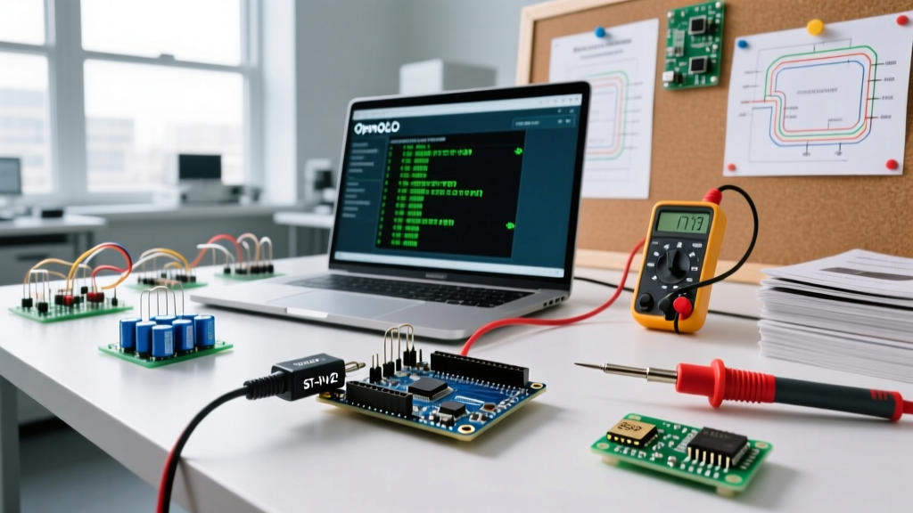
Before rewriting your sketch, cross-reference your serial monitor output and multimeter readings against this diagnostic matrix to isolate the root cause of your pin misconfiguration.
| Symptom Observed | Code Snippet | Hardware Reality | Resolution Strategy |
|---|---|---|---|
| Wildly fluctuating values (0-1023) on an unconnected pin. | analogRead(A0); |
High-impedance ADC sample-and-hold capacitor retaining ambient electromagnetic noise. | Add a 10kΩ pull-down resistor to GND, or ignore the pin in software. |
| Output pin reads 0V or 5V, but never an intermediate voltage like 2.5V. | analogWrite(A1, 128); |
ATmega328P analog pins (A0-A5) lack hardware PWM or DAC capabilities. | Move the wire to a digital pin marked with a tilde (~) for PWM, or use a true DAC pin on the Uno R4. |
Sensor reads 0 until physical stimulus is halfway applied, then jumps. |
digitalRead(2); on an analog sensor. |
Digital pins only recognize binary thresholds (e.g., >3V for HIGH on 5V boards). | Rewire to an Ax pin and use analogRead() to capture the voltage gradient. |
| ADC values max out at 4095 prematurely or read 0 at low voltages. | analogRead(A0); on Nano ESP32. |
ESP32-S3 ADC hardware non-linearity near the 0V and 3.3V rails. | Restrict sensor output to the 0.2V - 3.0V linear window, or use an external I2C ADC. |
Error Case 1: The 'Ghost Voltage' on Unconnected Analog Pins
A frequent post on support forums involves a user reporting that their Arduino is 'broken' because an unconnected analog pin returns random values between 0 and 1023 (or 16383 on 14-bit boards). This is not a defect; it is a fundamental characteristic of high-impedance ADC inputs.
The Sample-and-Hold Capacitor Effect
Inside the microcontroller, the ADC uses a tiny internal sample-and-hold capacitor to temporarily store the voltage from the pin before converting it to a digital number. When an analog pin is left floating (unconnected), this capacitor retains the charge from the previous read or acts as an antenna, picking up 50Hz/60Hz mains hum and ambient electromagnetic interference from your body and nearby wiring.
The Fix: If you must leave an analog pin unconnected but your code iterates through all pins, tie the unused pin to GND using a 10kΩ resistor. This provides a safe discharge path for the internal capacitor without drawing excessive current. Never tie it directly to GND if there is a risk of a firmware bug accidentally setting the pin to OUTPUT HIGH, which would short the microcontroller and destroy the GPIO bank.
Error Case 2: The PWM vs. True Analog Output Trap
The naming convention of the Arduino API is notoriously misleading for beginners. The function analogWrite() does not output a true analog voltage on 99% of Arduino boards. Instead, it outputs a Pulse Width Modulation (PWM) square wave.
When you call analogWrite(9, 128); on a digital pin marked with a tilde (~), the pin rapidly switches between 0V and 5V (or 3.3V) at a frequency of roughly 490Hz to 980Hz. A digital multimeter set to DC voltage will average this out and display ~2.5V, tricking the user into thinking a true analog voltage is present. However, if you connect this pin to an audio amplifier or a sensitive analog control circuit, you will inject high-frequency square-wave noise, causing erratic behavior or overheating.
Board-Specific DAC Realities in 2026
- Arduino Uno R3 (ATmega328P): Zero true analog output pins. You must use an external DAC (like the MCP4725, approx $4.00) or an RC low-pass filter on a PWM pin to smooth the square wave into a DC voltage.
- Arduino Uno R4 Minima (Renesas RA4M1): Features a true 12-bit Digital-to-Analog Converter (DAC) on pin
A0. CallinganalogWrite(A0, 2048);here outputs a genuine, smooth 1.65V DC signal. Attempting this onA1will fail silently or revert to digital HIGH/LOW depending on the core version.
Error Case 3: VREF Mismatch and ADC Non-Linearity
The most destructive errors occur when mixing 5V and 3.3V logic ecosystems. The ADC calculates its digital return value based on a Voltage Reference (VREF). On a legacy 5V Uno R3, VREF is tied to the 5V USB rail. A reading of 1023 equals 5.0V.
If you connect a modern 3.3V sensor (like a BME280 analog breakout or a 3.3V hall-effect sensor) to a 5V analog pin, the maximum output of the sensor (3.3V) will only yield an ADC reading of roughly 675. You have just wasted 35% of your ADC resolution, resulting in noisy, low-fidelity data.
The ESP32-S3 ADC Non-Linearity Edge Case
If you are using the Arduino Nano ESP32, you are working with the ESP32-S3 chip. This chip features a 12-bit ADC (0-4095), but it suffers from well-documented hardware non-linearity at the extreme ends of its voltage range. Readings below 0.15V often clip to 0, and readings above 3.1V clip to 4095.
Expert Troubleshooting Tip: If your precision voltage divider or potentiometer sweep on a Nano ESP32 appears 'dead' at the physical extremes of the knob's rotation, the ADC is clipping. To fix this, design your voltage divider to output a restricted range of 0.2V to 3.0V, or bypass the internal ADC entirely by adding an Adafruit ADS1115 16-bit external I2C ADC module.
Hardware-Specific Pin Mapping Nightmares
As of 2026, relying on legacy ATmega328P assumptions will break your code on modern ARM and RISC-V based Arduinos. Here is how the hardware shift impacts analog vs digital pin configurations:
- Resolution Defaults: The Arduino Uno R4 Minima hardware supports a 14-bit ADC (0-16383). However, the default Arduino core masks this to 10-bit for backward compatibility. If you copy a sketch from a Teensy or Raspberry Pi Pico forum that includes
analogReadResolution(14);, your Uno R4 will suddenly output values up to 16383, breaking any downstream math that assumes a 1023 maximum. - Pin Aliasing: On the Nano ESP32, the silkscreen labels (A0, A1, etc.) are logical aliases mapped by the Arduino core to the underlying ESP32-S3 GPIO numbers. Using raw GPIO numbers in
analogRead()can sometimes bypass the core's ADC calibration routines, leading to inaccurate voltage translations. Always use theAxaliases as defined in the Arduino's official analogRead() documentation. - Current Sourcing Limits: Digital pins on the Uno R4 (Renesas RA4M1) can source significantly less current per pin (approx 8mA) compared to the legacy Uno R3 (20mA). Driving a standard 20mA relay module directly from an Uno R4 digital pin without a MOSFET driver will cause brownouts and ADC read errors on adjacent analog pins due to voltage sag on the internal power rails.
Summary Checklist for Upload & Compile Errors
Before uploading your sketch and blaming the hardware, run through this 4-point diagnostic checklist:
- Verify the Silkscreen: Are you using
analogWrite()on a pin without a~symbol? (Unless using a dedicated DAC pin on the R4/ESP32, this is an error). - Check VREF Math: Does your voltage calculation formula match the board's logic level? (e.g.,
volts = raw * (3.3 / 4095.0);for Nano ESP32, not5.0 / 1023.0). - Inspect the Wiring: Are analog sensors wired to digital-only pins (like D0-D13 on legacy Unos)? Move them to the A0-A5 header.
- Mitigate Noise: If analog readings jitter by ±5 units, add a 0.1μF ceramic capacitor between the analog input pin and GND to filter high-frequency switching noise from nearby digital traces.
By treating analog and digital pins not just as software variables, but as distinct physical hardware peripherals with specific electrical limitations, you can eliminate the vast majority of sensor integration errors in your microcontroller projects.