
The Core Configuration: Why Direct Connection Fails
Learning how to connect LED Arduino circuits is the foundational rite of passage for every embedded systems engineer and maker. However, a surprising number of beginners skip the critical configuration step of current limiting, plugging a 5mm LED directly into a 5V GPIO pin and ground. While the LED may illuminate brilliantly for a few seconds, this configuration violates the fundamental electrical limits of the microcontroller.
The ATmega328P (found in the classic Arduino Uno R3) and the RA4M1 (found in the newer Uno R4) have strict current sourcing and sinking limits. According to the Arduino Digital Pins Foundation Guide, the absolute maximum current per I/O pin is 40mA, but the recommended continuous operating current is 20mA. Furthermore, the total current draw across all VCC and GND pins must not exceed 200mA. A standard LED without a current-limiting resistor will attempt to draw as much current as the power supply can provide, rapidly exceeding the 40mA threshold, overheating the silicon die inside the microcontroller, and permanently destroying the GPIO pin.
Selecting Your Components for Reliability
To build a robust circuit, you must select components with known datasheets rather than relying on generic, unbranded kits. For standard indication, the Kingbright WP7113 series (5mm through-hole LEDs) is an industry standard, offering consistent luminous intensity and predictable forward voltage drops. For resistors, the Yageo CFR-25JB series (1/4W carbon film resistors) provides excellent thermal stability and tight tolerance (±5%), ensuring your current calculations hold true in real-world thermal conditions.
LED Forward Voltage & Resistor Calculation Matrix
The configuration of your current-limiting resistor depends entirely on the LED's Forward Voltage (Vf) and your microcontroller's logic level voltage (Vs). Using Ohm's Law (R = (Vs - Vf) / If), we can determine the exact resistance required to maintain a safe 20mA (0.02A) current. Below is a configuration matrix for common LED colors across both 5V (Uno R3) and 3.3V (ESP32 / Uno R4 3.3V pins) logic systems.
| LED Color | Typical Vf (Volts) | Target If (mA) | Calculated Resistor (5V Logic) | Calculated Resistor (3.3V Logic) |
|---|---|---|---|---|
| Red | 2.0V | 20mA | 150Ω (Use 150Ω or 220Ω) | 65Ω (Use 68Ω) |
| Yellow | 2.1V | 20mA | 145Ω (Use 150Ω) | 60Ω (Use 68Ω) |
| Green | 3.3V | 20mA | 85Ω (Use 100Ω) | Cannot drive directly* |
| Blue / White | 3.2V - 3.4V | 20mA | 80Ω (Use 100Ω) | Cannot drive directly* |
*Note: Blue, White, and pure Green LEDs have a forward voltage higher than 3.3V. If you are using a 3.3V microcontroller, you cannot power these directly from a GPIO pin without a boost converter or a transistor switching a 5V rail.
Step-by-Step Physical Wiring Configuration
Proper physical routing on a breadboard prevents intermittent connections and short circuits. Follow this precise sequence for a standard digital pin configuration:
- Identify the Pins: Locate the Anode (positive, longer leg, rounded edge) and Cathode (negative, shorter leg, flat edge) of the LED. As detailed in the SparkFun Light Emitting Diodes (LEDs) Tutorial, the internal structure also reveals the cathode as the larger, anvil-shaped metal piece inside the epoxy dome.
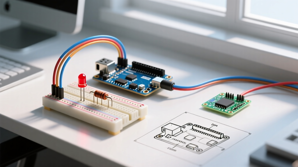
- Insert the Resistor: Plug one leg of your calculated resistor (e.g., 220Ω for a Red LED on 5V) into the digital output pin (e.g., Pin 8) row on the breadboard. Plug the other leg into an empty row.
- Bridge the LED: Insert the LED Anode into the same row as the resistor's second leg. Insert the Cathode into an adjacent row.
- Complete the Circuit: Use a jumper wire to connect the Cathode row to the breadboard's ground (GND) rail, and ensure the GND rail is tied to the Arduino's GND pin.
Software Configuration: Digital vs. PWM Control
Once the hardware is configured, the software must be written to match. For simple on/off states, digital configuration is sufficient. However, if you wish to configure the LED for dimming or breathing effects, you must route the anode to a PWM-capable pin (marked with a ~ on the Uno, such as Pin 9) and use analogWrite().
const int ledPin = 9; // PWM capable pin

void setup() {
  pinMode(ledPin, OUTPUT);
}

void loop() {
  // Configuration for a smooth 2.5-second breathing effect
  for (int brightness = 0; brightness <= 255; brightness += 5) {
    analogWrite(ledPin, brightness);
    delay(50);
  }
  for (int brightness = 255; brightness >= 0; brightness -= 5) {
    analogWrite(ledPin, brightness);
    delay(50);
  }
}
Advanced Configurations: High-Power and Addressable LEDs
Standard 5mm LEDs are limited to roughly 20mA. If your project requires high-lumen output (e.g., a 1W Star LED drawing 350mA) or complex animations, your configuration must change drastically.
Driving High-Power LEDs via Logic-Level MOSFETs
Never drive a high-power LED directly from an Arduino GPIO. Instead, configure an N-channel logic-level MOSFET, such as the IRLZ44N. Connect the Arduino PWM pin to the MOSFET's Gate via a 150Ω resistor, connect the Source to GND, and place the high-power LED (with its own dedicated heatsink and constant-current driver or appropriately rated power resistor) between the 5V/12V external power supply and the MOSFET's Drain. This isolates the high current from the delicate microcontroller logic.
Addressable RGB Configurations (WS2812B)
If you are configuring addressable LEDs like the WS2812B (NeoPixel), the wiring paradigm shifts entirely. These require a 5V power rail, a GND connection, and a single data line. Crucially, you must place a 300Ω to 500Ω resistor on the data line between the Arduino pin and the first LED's DIN pin to prevent voltage spikes from corrupting the data signal. For comprehensive wiring matrices for these specific ICs, refer to the Adafruit NeoPixel Überguide.
Troubleshooting Common Configuration Errors
Even with careful planning, hardware configurations can fail. Use this diagnostic checklist to identify edge cases:
- LED is Extremely Dim: You are likely using a PWM pin but calling
digitalWrite(pin, HIGH)in a way that conflicts with a lingeringanalogWrite()state, or your resistor value is too high (e.g., using a 10kΩ instead of 220Ω). Verify the resistor color bands. - Arduino Resets When LED Turns On: This indicates a brownout. The LED (or LED strip) is pulling too much current from the Arduino's onboard 5V voltage regulator, causing the voltage to drop below the microcontroller's minimum operating threshold. You must configure an external, dedicated power supply for the LEDs, sharing only a common ground with the Arduino.
- LED Flickers Erratically: This is often caused by a floating pin or a loose breadboard connection. Ensure the GPIO pin is explicitly declared as an
OUTPUTin thesetup()function. If using long jumper wires, electromagnetic interference (EMI) may be corrupting the signal; twist your data and ground wires together to cancel out noise. - Microcontroller Gets Hot to the Touch: Immediate shutdown required. You have likely wired the LED backward (shorting 5V to GND through the microcontroller's internal protection diodes) or omitted the current-limiting resistor entirely, causing the GPIO pin to source excessive current.
Expert Insight: Always configure your multimeter to measure current (in series) when testing a new LED circuit for the first time. Verifying that the actual current draw sits comfortably between 15mA and 20mA before deploying the code to a permanent soldered PCB will save you from catastrophic component failure and hours of debugging.