
Mastering the Infrared Remote Control Arduino Interface
Interfacing an infrared remote control Arduino setup is one of the most rewarding entry points into embedded systems. Whether you are building a motorized camera slider, a smart home relay controller, or a custom media center, decoding IR signals allows you to repurpose cheap, ubiquitous hardware. In 2026, the landscape of IR decoding has matured significantly, largely driven by major updates to the industry-standard IRremote library (v4.x and beyond) and the availability of highly resilient receiver diodes.
This comprehensive tutorial will guide you through component selection, precise wiring, protocol decoding, and advanced troubleshooting to ensure your infrared remote control Arduino project operates flawlessly in real-world environments.
Bill of Materials (BOM) & Component Selection
Before writing a single line of code, selecting the right IR receiver is critical. Not all 38kHz receivers are created equal, and choosing the wrong one can lead to phantom triggers caused by ambient lighting.
- Microcontroller: Arduino Uno R4 Minima or classic Uno R3 (Approx. $15 - $22). The R4 Minima offers faster processing for tight timing loops.
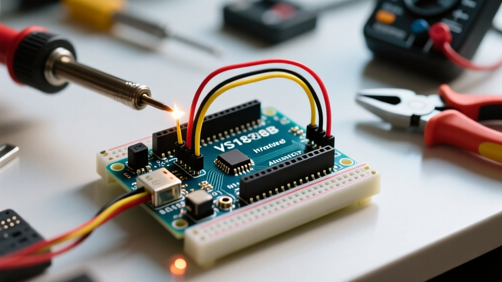
- IR Receiver (Budget): VS1838B 38kHz Receiver Module. A 10-pack costs around $6.50. Excellent for indoor, controlled lighting environments.
- IR Receiver (Premium): Vishay TSOP38238. Costs about $1.20 each. Features an integrated AGC (Automatic Gain Control) filter specifically designed to reject optical noise from CFL and LED bulbs.
- IR Remote: Any standard NEC, RC5, or RC6 remote. A generic 24-key RGB LED remote ($2.00) or an old Apple TV remote are excellent test subjects.
- Wiring: 22 AWG solid core jumper wires and a half-size breadboard.
Hardware Wiring: VS1838B vs TSOP38238
The wiring for a standard infrared remote control Arduino setup is straightforward, but voltage logic levels must be respected to prevent GPIO damage, especially if you migrate to 3.3V microcontrollers like the ESP32 or Arduino Nano 33 IoT.
| Receiver Pin | Arduino Uno R3/R4 (5V Logic) | ESP32 / Nano 33 IoT (3.3V Logic) | Function |
|---|---|---|---|
| GND | GND | GND | Common Ground |
| VCC | 5V | 3.3V | Power Supply (2.7V - 5.5V range) |
| DATA / OUT | Digital Pin 2 | GPIO 15 (or any 3.3V pin) | Demodulated Signal Output |
Expert Tip: Never power a VS1838B module with 5V if your microcontroller's GPIO pins are strictly rated for 3.3V. The DATA pin will output 5V logic HIGH, which can permanently degrade the MCU's input protection diodes over time. Always match VCC to the MCU's native logic level.
Step 1: Software Setup and Library Migration
The most common pitfall in 2026 is using outdated code written for IRremote v2.x or v3.x. The library underwent a massive architectural rewrite in v4.x to improve memory management and multi-protocol support.
- Open the Arduino IDE and navigate to Sketch > Include Library > Manage Libraries.
- Search for IRremote by shirriff, ArminJo, and contributors.
- Install the latest v4.x release. (For deeper technical documentation, refer to the Arduino-IRremote Official Repository).
- Critical: If you are using an older Arduino IDE version, ensure you delete the default
RobotIRremotelibrary from your core libraries folder, as it causes severe namespace conflicts with the modern IRremote library.
Step 2: The Universal Decoder Sketch
Upload the following sketch to your Arduino. This code initializes the hardware timer, listens for demodulated pulses, and prints the raw hex data and protocol type to the Serial Monitor.
#include

const int IR_RECEIVE_PIN = 2;

void setup() {
  Serial.begin(115200);
  while (!Serial);

  // Initialize the IR receiver with LED feedback enabled
  IrReceiver.begin(IR_RECEIVE_PIN, ENABLE_LED_FEEDBACK);

  Serial.println(F("IR Receiver Ready. Waiting for signals..."));
}

void loop() {
  if (IrReceiver.decode()) {
    // Print a concise summary of the decoded data
    IrReceiver.printIRResultShort(&Serial);

    // Print the raw hex value for manual mapping
    Serial.print(F("Hex Value: "));
    Serial.println(IrReceiver.decodedIRData.decodedRawData, HEX);

    // Resume receiving
    IrReceiver.resume();
  }
}
Understanding the Serial Output
When you press a button on your remote, the Serial Monitor (set to 115200 baud) will output a string similar to: Protocol=NEC Address=0x0 Command=0x18 Raw-Data=0xE718FF00 32 bits LSB first. The Raw-Data is your unique hex identifier for that specific button.
Step 3: Protocol Identification Matrix
Different manufacturers use different encoding schemes. Understanding these helps in filtering out ghost signals and structuring your switch/case statements in your final application logic.
| Protocol | Typical Brands | Bit Length | Carrier Freq | Timing Signature |
|---|---|---|---|---|
| NEC | Generic RGB, Samsung, DIY kits | 32 bits | 38 kHz | 9ms AGC leader pulse, 4.5ms space |
| RC5 | Philips, older European audio | 14 bits | 36 kHz | Manchester encoding, 1.7ms bit time |
| RC6 | Microsoft MCE, Xbox | 20-36 bits | 36 kHz | 2.6ms leader, Manchester encoding |
| Sony (SIRC) | Sony Bravia, PlayStation | 12, 15, or 20 bits | 40 kHz | 2.4ms leader pulse, 600us space |
For a deeper dive into how these protocols modulate light, the Adafruit IR Sensor Guide provides excellent oscilloscope visualizations of the carrier wave and envelope.
Advanced Troubleshooting & Edge Cases
Even with perfect wiring, environmental factors can ruin an infrared remote control Arduino project. Here is how to solve the most common field failures.
1. Ambient Optical Noise (The CFL/LED Problem)
Symptom: The Serial Monitor spams random hex codes or the receiver ignores your remote entirely. Cause: Compact Fluorescent Lamps (CFLs) and cheap, unshielded LED bulbs emit broadband infrared noise. Some flicker at high frequencies that overwhelm the VS1838B's basic AGC circuit. Solution: Upgrade to the Vishay TSOP38238, which features a proprietary filter against optical noise. Alternatively, place a piece of dark IR-pass acrylic (like an old floppy disk shutter) over the VS1838B to block visible light spectrum interference.
2. Carrier Frequency Mismatch
Symptom: The receiver only decodes signals when the remote is less than 2 inches away. Cause: You are using a 38kHz receiver (VS1838B) with a 40kHz remote (common with Sony SIRC protocol). The bandpass filter inside the receiver is attenuating the signal by 6dB or more. Solution: Check your remote's protocol. If it is Sony, purchase a 40kHz specific receiver like the TSOP4440. The SparkFun IR Control Hookup Guide details how to identify carrier frequencies using an oscilloscope if the protocol is unknown.
3. Power Supply Brownouts
Symptom: The Arduino resets or behaves erratically when the IR receiver triggers a relay. Cause: Mechanical relays draw a massive inrush current (often >100mA) when the coil energizes. If the Arduino's 5V rail is shared without adequate decoupling, the voltage drops below the MCU's brownout detection threshold (typically 2.7V for ATmega328P). Solution: Never power inductive loads directly from the Arduino's 5V pin. Use an external 5V buck converter for relays, and add a 100uF electrolytic capacitor across the VCC and GND pins of the IR receiver module to smooth out local transient voltage dips.
Summary
Building a reliable infrared remote control Arduino setup requires more than just copying a basic sketch. By selecting the correct receiver diode for your environment (VS1838B for clean labs, TSOP38238 for noisy living rooms), respecting logic-level voltages, and utilizing the modern IRremote v4.x syntax, you can create robust, commercial-grade IR interfaces. Whether you are decoding a 32-bit NEC command or filtering out 36kHz RC5 noise, the principles outlined here will ensure your microcontroller responds accurately every time.