
Why Your Arduino Needs an External Power Supply Module
The Arduino Uno R3 and Nano are phenomenal microcontrollers, but their onboard voltage regulators are fundamentally limited. The standard NCP1117 linear regulator found on most genuine and clone boards can safely dissipate only about 1W to 1.5W of heat before triggering thermal shutdown. If you attempt to power high-current peripherals like MG996R servo motors, NEMA 17 stepper motors, or WS2812B NeoPixel strips directly from the Arduino's 5V pin, you will quickly exceed this thermal limit, resulting in erratic behavior, brownouts, or permanent silicon damage.
To build robust, real-world embedded systems, you must offload power delivery to a dedicated external circuit. This guide details exactly how to configure a power supply module for Arduino projects, covering the ubiquitous MB102 breadboard module, high-current switching buck converters, and the modern 2026 standard: USB-C Power Delivery (PD) trigger boards.
Configuring the MB102 Breadboard Power Supply Module
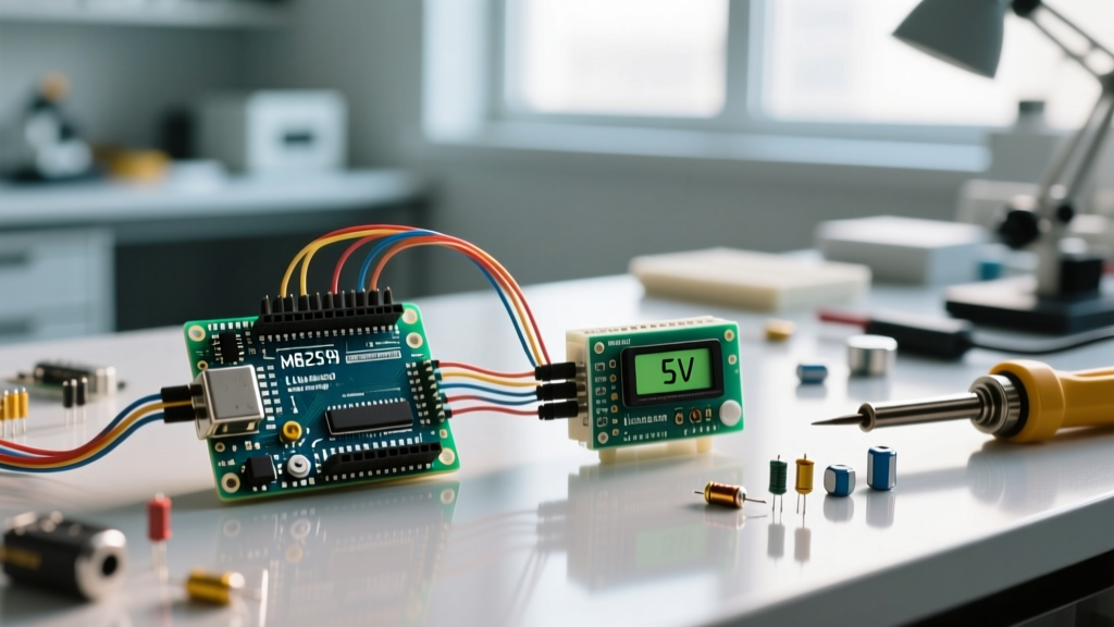
The MB102 is the most common entry-level power supply module for Arduino breadboarding. It plugs directly into standard solderless breadboard power rails and features a DC barrel jack (6.5V–12V input) and a USB Type-A port (5V input). It utilizes AMS1117 Linear Dropout (LDO) regulators to provide selectable 3.3V or 5V outputs via onboard jumpers.
The Thermal Trap: Understanding LDO Limitations
While the MB102 is rated for 700mA on paper, real-world physics dictates a much lower safe continuous current. The AMS1117 is a linear regulator, meaning it burns excess voltage as heat. According to the AMS1117 datasheet, the SOT-223 package has a junction-to-ambient thermal resistance of roughly 60°C/W.
The Math Behind the Magic Smoke:
If you input 9V and output 5V at 500mA, the power dissipated is (9V - 5V) × 0.5A = 2.0W. Multiply 2.0W by 60°C/W, and the chip's internal temperature rises 120°C above ambient room temperature. At a 25°C room, the junction hits 145°C, instantly triggering the IC's internal thermal shutdown.
Safe Configuration Steps for the MB102
- Set the Voltage Jumpers: Place the black plastic jumpers on the VCC pins to select either 3.3V or 5V for each independent rail. Leave them off if you want the rail unpowered.
- Choose the Right Input Source: To minimize heat, keep the input voltage as close to the output voltage as possible. If you need 5V out, power the MB102 via the USB port (5V in) rather than a 12V DC wall adapter. This bypasses the 5V LDO entirely, allowing you to safely draw up to the USB source's limit (usually 1A–2A).
- Add Bulk Capacitance: Solder or plug a 100µF electrolytic capacitor across the breadboard power rails near your load to absorb transient current spikes when microcontrollers switch I/O pins or sensors wake from sleep.
High-Current Configuration: The LM2596 Buck Converter
When your project requires 1A to 3A of continuous current—such as driving a robotic arm with four servos or a 60-LED NeoPixel ring—linear regulators are obsolete. You must use a switching buck converter. The LM2596 module is the industry workhorse for this exact scenario.
Unlike LDOs, switching converters step down voltage by rapidly toggling a MOSFET and storing energy in an inductor, achieving 85% to 92% efficiency. This means a 3A load at 5V drawing from a 12V source will only generate a fraction of the heat compared to an LDO. For deep technical specifications on switching frequencies and inductor saturation, refer to the Texas Instruments LM2596 datasheet.
Step-by-Step LM2596 Voltage Tuning
Most LM2596 modules ship from the factory with the output voltage set to the input voltage or an arbitrary default. You must tune it before connecting it to your Arduino or sensors.
- Step 1: Connect your DC power source (e.g., a 12V laptop brick) to the IN+ and IN- screw terminals.
- Step 2: Connect a digital multimeter (DMM) probes to the OUT+ and OUT- terminals. Set the DMM to DC Voltage.
- Step 3: Using a small ceramic flathead screwdriver, turn the brass screw on the blue potentiometer. Turn counter-clockwise to decrease voltage and clockwise to increase it.
- Step 4: The potentiometer is highly sensitive, often requiring 10 to 15 full rotations to sweep the 1.25V to 35V range. Turn slowly and wait 1-2 seconds between turns for the DMM reading to stabilize.
- Step 5: Once you hit exactly 5.00V (or 3.30V), apply a dab of clear nail polish or Loctite 495 over the screw to prevent mechanical vibration from altering the resistance over time.
The 2026 Standard: USB-C Power Delivery (PD) Trigger Modules
As of 2026, the maker community has heavily pivoted away from bulky 12V DC barrel adapters toward USB-C Power Delivery (PD) ecosystems. Using a USB-C PD trigger module (such as those based on the IP2721 or CH224K chips) allows you to negotiate specific voltages (5V, 9V, 12V, 15V, or 20V) directly from a standard 65W or 100W laptop GaN charger.
Configuration Workflow: You solder a USB-C PD trigger board to request 5V at 3A. You then plug your modern GaN charger into it. This provides a incredibly stable, high-current 5V rail directly to your breadboard or custom PCB, completely eliminating the need for a step-down buck converter if your system operates at 5V. If you need 12V for motors and 5V for logic, you use a PD trigger to request 12V, feed that to an LM2596 to create a 5V logic rail, and use the raw 12V for the motor drivers.
Module Comparison Matrix
Selecting the correct power supply module for Arduino depends entirely on your load profile. Use the table below to make an informed engineering decision.
| Module Type | Topology | Max Continuous Current | Efficiency | Best Use Case | Approx. Cost (2026) |
|---|---|---|---|---|---|
| MB102 Breadboard | Linear (LDO) | ~300mA (Safe) | Low (30-60%) | Logic ICs, I2C sensors, LEDs | $1.50 - $3.00 |
| LM2596 Buck | Switching | 2.0A - 3.0A | High (85-92%) | Servos, Steppers, Audio Amps | $2.50 - $4.50 |
| XL4015 5A Buck | Switching | 4.0A - 5.0A | High (90-95%) | High-power LED arrays, Motors | $4.00 - $7.00 |
| USB-C PD Trigger | Negotiation IC | Up to 5A (at 5V) | N/A (Pass-through) | Modern portable IoT, GaN setups | $2.00 - $5.00 |
The Golden Rule: Establishing a Common Ground
The most frequent point of failure when configuring external power modules is neglecting the common ground. If your Arduino is powered via USB from your laptop, and your servo motors are powered by an LM2596 module plugged into a wall adapter, you have two isolated circuits.
When the Arduino sends a PWM signal from Pin 9 to the servo's signal wire, the voltage is referenced to the Arduino's ground. If the servo's ground is floating relative to the Arduino's ground, the signal pin will experience unpredictable voltage differentials. This results in severe servo jitter, communication failures, or worse: current backfeeding through the signal pin and frying the ATmega328P's I/O port.
How to Wire the Common Ground
- Run a dedicated wire from the GND pin on the Arduino to the OUT- (Negative) terminal on the LM2596 or the negative rail of the MB102.
- Ensure this ground wire is of sufficient gauge (22 AWG or thicker for currents above 1A) to prevent ground bounce.
- Never connect the positive voltage output of the external module to the Arduino's 5V pin if the Arduino is simultaneously powered via USB or the VIN pin. This will backfeed power into the USB controller or onboard regulator, causing catastrophic failure.
Troubleshooting Edge Cases and Failure Modes
Even with perfect wiring, power delivery in embedded systems presents unique challenges. Here is how to diagnose the most common issues:
1. ADC Noise and Sensor Inaccuracy
Switching regulators like the LM2596 operate at frequencies around 150kHz. This switching action introduces high-frequency ripple onto the DC output line. If you are reading analog sensors (like load cells or thermistors) using the Arduino's Analog-to-Digital Converter (ADC), this ripple will manifest as noisy, jumping values.
The Fix: Add a low-pass RC filter (e.g., a 100Ω resistor in series with the signal, and a 0.1µF ceramic capacitor to ground) at the ADC input pin. Additionally, place a 10µF ceramic capacitor directly across the output terminals of the buck converter to suppress high-frequency EMI.
2. Voltage Drop Under Load
If your LM2596 is tuned to 5.0V, but drops to 4.2V when a motor starts, you are experiencing voltage sag due to wire resistance and inductor saturation.
The Fix: Upgrade your wiring. Thin 28 AWG jumper wires have significant resistance. Use 18 AWG silicone wire for the main power trunks. Furthermore, verify that your input voltage is at least 2V higher than your desired output voltage to maintain the buck converter's dropout margin.
3. Inductive Kickback
When powering relays, solenoids, or DC motors directly from a power module, the sudden collapse of the magnetic field when the component turns off generates a massive reverse voltage spike (inductive kickback). This spike can easily exceed the 40V maximum input rating of the LM2596, destroying the IC.
The Fix: Always solder a flyback diode (such as a 1N4007 or Schottky 1N5819) in reverse bias across the terminals of any inductive load. For detailed wiring diagrams regarding high-current inductive loads, the Adafruit NeoPixel Überguide offers excellent visual references for managing transient spikes and power injection.
Final Configuration Checklist
Before applying power to your microcontroller, run through this mental checklist:
- [ ] External module voltage is verified with a multimeter before connecting to the Arduino.
- [ ] Common ground is established between the MCU and the external power source.
- [ ] Input voltage to switching regulators is within the specified limits (usually < 35V for LM2596).
- [ ] Flyback diodes are installed across all inductive loads.
- [ ] Bulk capacitance is present near high-current transient loads.
By treating power delivery as a primary engineering constraint rather than an afterthought, you ensure your Arduino projects transition reliably from the breadboard to permanent deployment.