
The Hidden Bottleneck: Why Cable Configuration Matters
When sourcing cables para arduino projects, many makers default to the cheapest bulk packs of pre-crimped jumper wires without considering the electrical realities of their specific circuit. While a 28 AWG Dupont wire is perfectly adequate for transmitting a 5mA logic signal from a pushbutton to an ATmega328P digital input, using that same wire to power a high-torque MG996R servo motor is a recipe for brownout resets and erratic behavior. Proper cable configuration encompasses wire gauge selection, connector pinout mapping, impedance matching for high-speed buses, and USB data line verification. This guide provides a deep-dive technical framework for configuring, selecting, and routing interconnects in both prototyping and permanent microcontroller deployments.
Wire Gauge (AWG) and Current Capacity Matrix
The American Wire Gauge (AWG) system dictates the physical cross-sectional area of the copper conductor, which directly correlates to its DC resistance and current-carrying capacity (ampacity). According to the DigiKey Wire Size Conversion Calculator and standard IPC-2221 guidelines, exceeding the ampacity of a micro-wire leads to excessive voltage drops and, in extreme cases, insulation melting. Below is the configuration matrix for standard microcontroller wiring.
| AWG Size | Max Current (Chassis) | Resistance (per 10m) | Primary Configuration Use Case |
|---|---|---|---|
| 28 AWG | 1.4 A | ~2.10 Ω | Breadboard jumpers, I2C/SPI logic signals, low-power sensor data lines. |
| 24 AWG | 3.5 A | ~0.84 Ω | Motor driver outputs (L298N), high-power LED strips (WS2812B), standard servo power. |
| 22 AWG | 5.0 A | ~0.53 Ω | Main 5V/12V power rails, stepper motor phases (A4988/DRV8825), LiPo battery leads. |
| 20 AWG | 7.0 A | ~0.33 Ω | High-current DC motor feeds, main power entry from bench supplies to distribution boards. |
Edge Case: The Servo Brownout Failure Mode
A common failure mode occurs when makers use 28 AWG cables to power multiple servos from the Arduino Uno's onboard 5V regulator. A single MG996R servo can draw up to 2.5A under stall conditions. If you push even 1A through a 30cm run of 28 AWG wire, the voltage drop (V = I × R) will be approximately 0.12V. While this seems negligible, standard USB ports often sag to 4.7V under load. The cumulative drop across the USB cable, the onboard polyfuse, and the 28 AWG jumper can push the voltage at the servo below 4.2V, while simultaneously dragging the ATmega328P VCC below its brownout detection threshold (typically 4.3V for the default fuse settings), causing the MCU to endlessly reboot.
Connector Ecosystem: Dupont vs. JST Configurations
Selecting the correct terminal housing is just as critical as the wire gauge. The physical pitch (distance between pin centers) and locking mechanisms define the reliability of your cables para arduino harness.
- Dupont (2.54mm Pitch): The ubiquitous standard for breadboarding and male/female header connections. Configuration Warning: Dupont connectors lack a positive locking mechanism. In high-vibration environments (robotics, drones), they will slowly back out. Always secure Dupont ribbons with Kapton tape or hot glue in permanent deployments.
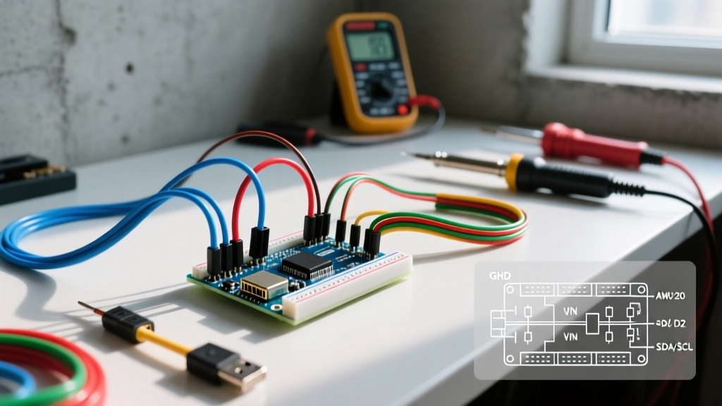
- JST-PH (2.0mm Pitch): The standard for modern sensor ecosystems. Adafruit's STEMMA QT and SparkFun's Qwiic systems utilize a 4-pin JST-PH connector configured specifically for I2C (GND, 3V3, SDA, SCL). The PH series features a friction lock that prevents accidental disconnection.
- JST-XH (2.5mm Pitch): Heavier duty than the PH series, XH connectors are the standard configuration for LiPo battery balance leads and stepper motor wiring harnesses. They are rated for up to 3A per circuit and feature a robust snap-lock.
USB Cable Configuration: Resolving the "Charge-Only" Trap
One of the most frequent support tickets in the maker community involves an Arduino failing to appear in the Arduino IDE port menu. The culprit is almost always an improperly configured USB cable. A standard USB 2.0 Type-A to Type-B (or Micro-USB) cable contains four internal conductors:
- VBUS (Red): +5V Power
- GND (Black): Ground Return
- D- (White): Data Minus
- D+ (Green): Data Plus
Cheap promotional cables often omit the D- and D+ wires to save on copper costs, functioning strictly as power delivery cables. If you are configuring a permanent installation and need to verify a cable's data capability without plugging it into a PC, use a digital multimeter in continuity mode. Probe the outer two pins of the USB Type-A connector (VBUS and GND) and the inner two pins (D- and D+). If the inner pins show no continuity to the opposite end, the cable is charge-only and must be discarded for MCU programming purposes.
High-Speed Bus Routing: I2C and SPI Cable Limits
When extending sensors away from the microcontroller, the physical configuration of the cable alters the bus capacitance. The official NXP I2C-bus specification (UM10204) mandates a maximum bus capacitance of 400 pF for standard mode (100 kHz) and fast mode (400 kHz) operation.
Calculating Cable Capacitance
Standard unshielded 28 AWG ribbon cable exhibits a parasitic capacitance of approximately 15 pF to 20 pF per foot (30 cm) between adjacent conductors. If you configure a 2-meter (6.5 ft) ribbon cable for an I2C temperature sensor, the cable alone introduces roughly 100 pF to 130 pF of capacitance. Add the pin capacitance of the MCU, the sensor, and any breadboard contacts, and you quickly approach the 400 pF limit. Exceeding this limit results in rounded signal edges, causing the I2C bus to hang or return corrupted hex addresses.
Pro-Tip for Long-Run I2C: If your physical configuration requires running I2C cables beyond 1 meter, do not use standard ribbon cable. Instead, configure the bus using CAT5e twisted-pair Ethernet cable. Assign SDA and GND to one twisted pair (e.g., Orange/Orange-White), and SCL and 3V3 to another twisted pair (e.g., Green/Green-White). The twisting drastically reduces electromagnetic interference (EMI) and crosstalk between the clock and data lines.
Step-by-Step: Crimping Custom JST-PH Harnesses
For professional-grade cables para arduino assemblies, learning to crimp your own JST-PH connectors is essential. Pre-crimped wires are often overpriced and limit your routing geometry. According to the SparkFun Working with Wire tutorial, a proper crimp relies on cold-welding the copper to the terminal, not just piercing it.
- Strip the Insulation: Use a precision wire stripper (like the Hakko CHP 170) to remove exactly 2.0mm of insulation from a 24 AWG or 26 AWG stranded wire. Exposing too much bare wire will cause a short when inserted into the housing.
- Position the Terminal: Place the JST-PH terminal into the correct jaw of your crimping tool. For 2.0mm pitch connectors, the IWISS SN-01BM or SN-28B (with the correct die) is highly recommended. Align the terminal so the conductor crimp wings are in the smaller jaw and the insulation wings are in the larger jaw.
- Execute the Crimp: Squeeze the tool until the ratchet releases. The conductor wings should fold inward tightly, gripping the copper strands without cutting them, while the insulation wings wrap securely around the wire jacket.
- The Pull Test: Tug firmly on the wire. A correctly configured crimp will withstand 15-20 lbs of pull force before the wire breaks; a failed crimp will slide out immediately.
- Housing Insertion: Push the crimped terminal into the JST-PH plastic housing until you hear a distinct "click." The locking tang on the metal terminal must catch the plastic ramp inside the housing. Pull back gently to verify it is seated.
Summary: Building Reliable Interconnects
Configuring the right cables for your microcontroller projects transitions your work from fragile breadboard prototypes to robust, field-ready electronics. By respecting AWG current limits, utilizing locking JST connectors for deployment, verifying USB data line continuity, and managing bus capacitance on high-speed protocols, you eliminate an entire class of intermittent hardware bugs. Always prioritize signal integrity and power delivery headroom when designing your wiring harnesses.