
The Physics of the Pushbutton: Why Simple Circuits Fail
Designing a reliable button circuit Arduino project seems like the most trivial task in electronics. You connect a switch to a digital pin, read the state, and trigger an action. However, beginners quickly discover that a single physical button press often registers as dozens of rapid, erratic triggers. To build robust microcontroller interfaces in 2026, you must understand two fundamental electrical concepts: floating pins and mechanical switch bounce.
Understanding Floating Inputs
A microcontroller pin configured as an input has extremely high impedance (often >100 MΩ on the ATmega328P). If a pushbutton is wired directly between the pin and ground without a reference voltage, the pin is left 'floating' when the switch is open. In this state, the pin acts as an antenna, picking up electromagnetic interference (EMI) from nearby wires, motors, or even your body. The Arduino will read random HIGH and LOW states, leading to unpredictable behavior.
Mechanical Bounce in Tactile Switches
When you press a standard tactile switch—such as the ubiquitous Omron B3F-1000 (typically costing around $0.12 in bulk)—the internal metal contacts do not mate perfectly on the first impact. The microscopic spring steel bounces against the contact pad several times before settling. This phenomenon, known as contact bounce, typically lasts between 1ms and 5ms. Because an Arduino executes millions of instructions per second, it reads these physical bounces as distinct, rapid button presses.
Pull-Down vs. Pull-Up Resistor Configurations
To eliminate floating pins, you must use a resistor to 'pull' the pin to a known voltage state when the button is not pressed. There are three primary ways to configure a button circuit for Arduino.
| Configuration | Resting State | Pressed State | Resistor Value | Best Use Case |
|---|---|---|---|---|
| External Pull-Down | LOW (0V) | HIGH (5V/3.3V) | 10kΩ to VCC | Beginner learning, explicit logic mapping |
| External Pull-Up | HIGH (5V/3.3V) | LOW (0V) | 10kΩ to GND | Industrial panels, long wire runs |
| Internal Pull-Up | HIGH (5V/3.3V) | LOW (0V) | ~20kΩ-50kΩ (Internal) | Standard prototyping, PCB space saving |
According to the official Arduino PinMode documentation, the ATmega328P features built-in pull-up resistors that can be activated via software using pinMode(pin, INPUT_PULLUP);. This eliminates the need for external resistors in most standard hobbyist applications. However, the internal resistors have a wide tolerance (20kΩ to 50kΩ) and can be too weak for environments with high EMI or when using long cable runs exceeding 30cm.
Step-by-Step: Wiring the Button Circuit
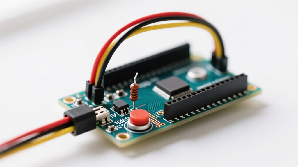
For the most reliable and breadboard-friendly setup, we recommend using the internal pull-up configuration. Here is the exact wiring procedure:
- Identify Switch Pins: Standard 6mm tactile switches have four pins. Internally, pins on the same side of the switch are connected. Always wire across the diagonal to ensure the circuit is broken when the switch is at rest.
- Connect to Ground: Run a jumper wire from one diagonal pin of the tactile switch directly to the Arduino GND pin.
- Connect to Digital I/O: Run a second jumper wire from the opposite diagonal pin to your chosen digital input (e.g., Digital Pin 2).
- Configure Software: In your
setup()function, declarepinMode(2, INPUT_PULLUP);. This connects the internal 20kΩ+ resistor to 5V, keeping the pin HIGH until the button bridges it to GND.
Expert Tip: When using internal pull-ups, remember that the logic is inverted. A physical press reads as
LOW, and a release reads asHIGH. Adjust yourif (digitalRead(pin) == LOW)conditionals accordingly.
Solving Switch Bounce: Hardware vs. Software
Once the pin is stabilized, you must address mechanical bounce. You can filter this noise using either hardware components or software algorithms. As detailed in Jack Ganssle's definitive guide to debouncing, the choice depends on your CPU overhead and hardware constraints.
Hardware Debouncing (RC Filter)
Hardware debouncing uses a Resistor-Capacitor (RC) network to smooth the voltage transitions. By placing a 100nF (0.1µF) ceramic capacitor in parallel with the switch, the capacitor absorbs the rapid voltage spikes caused by bouncing.
The time constant ($\tau$) is calculated as $\tau = R \times C$. With a 10kΩ pull-up resistor and a 100nF capacitor, $\tau = 1ms$. It takes roughly $3\tau$ (3ms) for the capacitor to charge or discharge enough for the Arduino to register a definitive logic state change. For extremely noisy industrial environments, engineers often pair the RC filter with a 74HC14 Schmitt Trigger hex inverter ($0.45 per IC) to provide sharp, hysteresis-based digital edges.
Software Debouncing (The Bounce2 Library)
In 2026, software debouncing remains the most popular approach because it requires zero extra components. While the official Arduino Debounce tutorial demonstrates a basic millis() implementation, managing multiple buttons with raw timing code quickly becomes a tangled mess of variables.
Instead, use the Bounce2 library by Thomas Ouellet Fredericks. It abstracts the timing logic and provides robust state-change detection.
#include <Bounce2.h>

Bounce debouncer = Bounce();
const int BUTTON_PIN = 2;

void setup() {
  pinMode(BUTTON_PIN, INPUT_PULLUP);
  debouncer.attach(BUTTON_PIN);
  debouncer.interval(5); // 5ms debounce window
}

void loop() {
  debouncer.update();
  if (debouncer.fell()) {
    // Executes exactly once per physical press
    Serial.println('Button Pressed');
  }
}
The debouncer.fell() method is crucial. It only returns true on the exact millisecond the signal transitions from HIGH to LOW, completely ignoring the subsequent bounces and the held-down state.
Common Failure Modes and Troubleshooting
Even with proper pull-ups and debouncing, button circuits can fail in the field. Watch out for these specific edge cases:
- Contact Oxidation: In high-humidity environments, the internal contacts of cheap tactile switches oxidize, increasing contact resistance. If your Arduino is running on 3.3V (like an ESP32), a weak internal pull-up might not overcome the voltage drop across oxidized contacts. Solution: Use gold-plated switches or external 4.7kΩ pull-up resistors to increase current flow and burn through minor oxidation.
- Parasitic Capacitance on Long Wires: If your button is located more than 50cm away from the microcontroller, the wire itself acts as a capacitor. This can slow down the rising edge of the signal, causing the Arduino to misread the state. Solution: Use shielded twisted-pair cable and lower the external pull-up resistor value to 2.2kΩ to charge the parasitic capacitance faster.
- Ground Bounce from Inductive Loads: If your Arduino shares a ground plane with relays or motors, the sudden switching of those loads can cause a momentary spike in the ground reference (ground bounce). This spike can be misinterpreted by the MCU as a button press. Solution: Implement physical star-grounding topologies and add a 100µF electrolytic decoupling capacitor near the MCU power pins.
By respecting the physics of mechanical contacts and properly configuring your microcontroller's input impedance, you can transform a frustrating, erratic pushbutton into a rock-solid user interface.