
The Core Concept: Baud Rate vs. Bit Rate
When configuring serial communication on a microcontroller, the Serial.begin() function requires a specific numerical parameter. This parameter defines the baud rate in Arduino environments, dictating how fast data travels between your board and a host computer, sensor, or secondary MCU. However, a common misconception among makers is conflating baud rate with bit rate.
Historically, baud rate refers to the number of signal symbol changes per second. In modern digital UART (Universal Asynchronous Receiver-Transmitter) systems used by Arduino, each symbol represents exactly one bit. Therefore, a baud rate of 9600 means 9600 bits are transmitted per second. While the terms are practically interchangeable in standard Arduino serial communication, understanding the distinction is critical when dealing with advanced modulation schemes or multi-bit symbols in RF modules.
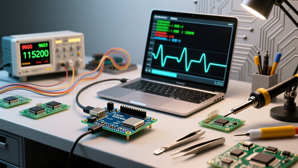
Expert Insight: Never assume higher baud rates are universally better. While 115200 or 500000 baud transfers data faster, higher frequencies are exponentially more susceptible to signal degradation, cable capacitance, and electromagnetic interference (EMI) over long wire runs.
The Anatomy of a Serial Frame: Calculating True Throughput
To truly master serial communication, you must account for protocol overhead. The default Arduino serial configuration is 8N1: 8 data bits, No parity, and 1 stop bit. However, UART also requires a start bit to synchronize the receiver's clock.
- Start Bit: 1 bit (always low)
- Data Bits: 8 bits (the actual payload)
- Parity Bit: 0 bits (in 8N1 mode)
- Stop Bit: 1 bit (always high)
This means every single byte (8 bits) of payload data requires 10 bits of physical transmission. If you set your baud rate in Arduino to 9600, your theoretical maximum throughput is not 9600 bytes per second, but rather 960 bytes per second (9600 / 10). When streaming high-frequency sensor data, such as a 3-axis accelerometer sampling at 1kHz, a 9600 baud connection will bottleneck and overflow the ATmega328P's 64-byte serial buffer, resulting in dropped packets.
Standard Baud Rates and Hardware Limits
While you can theoretically pass any integer to Serial.begin(), both the transmitting and receiving devices must agree on standard speeds to avoid synchronization errors. Below is a matrix of standard rates and their practical use cases in modern maker projects.
| Baud Rate | Bytes/Sec (8N1) | Primary Use Case | Max Reliable Distance (TTL/RS232) |
|---|---|---|---|
| 300 | 30 | Legacy telemetry, low-power RF wake-up | ~50 meters |
| 9600 | 960 | GPS modules (NMEA), basic Bluetooth HC-05 | ~15 meters |
| 57600 | 5760 | 3D Printer G-code streaming (legacy) | ~5 meters |
| 115200 | 11520 | Standard IDE Serial Monitor, ESP8266 boot logs | ~2 meters |
| 500000 | 50000 | High-speed data logging, fast TFT displays | < 1 meter (highly shielded) |
| 2000000 | 200000 | Native USB CDC (ESP32-S3, Teensy 4.1) | USB Cable Length Limit (~3m) |
The 16MHz Crystal Problem: UART Error Margins
One of the most heavily documented, yet frequently misunderstood, issues in the Arduino ecosystem involves the 16MHz crystal oscillator found on the Uno and Nano. The ATmega328P microcontroller generates its UART timing by dividing the system clock. Because 16,000,000 Hz does not divide cleanly into standard baud rates like 115200, hardware timing errors occur.
According to the Microchip ATmega328P Datasheet, the UART baud rate register (UBRR) calculates the speed using a specific formula. When targeting 115200 baud in normal speed mode, the actual generated baud rate is 111,111. This results in a -3.5% timing error. While many USB-to-Serial chips (like the FT232R) can tolerate this, cheaper clone chips (like the CH340 or CP2102) operating in noisy environments may fail to synchronize, outputting garbled text.
The U2X Solution: The Arduino core library intelligently mitigates this by setting the U2X (Double Speed) bit in the UCSRA register for 115200 baud. This changes the divisor, resulting in an actual baud rate of 117,647, shrinking the error to +2.1%, which is well within the safe ±4% tolerance required for reliable UART communication. For a deeper dive into how the Arduino IDE handles these hardware-level calculations, refer to the official Arduino Serial.begin() Reference.
Modern Architecture: Native USB vs. UART Bridges
As we look at the microcontroller landscape in 2026, the concept of "baud rate" is undergoing a paradigm shift. Legacy boards (Uno, Mega) rely on a hardware UART connected to a secondary USB-to-Serial bridge chip. The baud rate strictly governs the physical wire speed between the main MCU and the bridge.
Modern architectures like the Raspberry Pi RP2040 (Pico), ESP32-S3, and Teensy 4.1 feature Native USB CDC (Communications Device Class). When you call Serial.begin(115200) on an RP2040, the baud rate parameter is essentially ignored by the hardware. The data is packetized into USB bulk transfers, which operate at 12 Mbps (Full Speed) or 480 Mbps (High Speed). The host computer's serial terminal still requires you to select 115200 to open the COM port, but the physical transmission speed is dictated entirely by the USB bus negotiation, eliminating UART timing errors and buffer overflows entirely.
Troubleshooting Garbled Serial Output
If your Serial Monitor displays Wingdings, question marks, or random ASCII characters, the issue is almost always a synchronization or signal integrity failure. Follow this diagnostic matrix:
- Verify Software Matching: Ensure the integer in
Serial.begin()exactly matches the dropdown menu in the Arduino IDE Serial Monitor. A mismatch (e.g., 9600 vs 115200) is the cause of 90% of beginner errors. - Check the USB-to-Serial Chip: If using a third-party FTDI cable or a clone board with a CH340G chip, ensure you have the correct, up-to-date drivers installed for your OS. Outdated drivers can force incorrect hardware flow control (RTS/CTS), choking the data stream.
- Inspect Ground Loops: When communicating between two separate Arduino boards via TX/RX pins, they must share a common ground. Without a common ground reference, the voltage thresholds for logic HIGH and LOW will drift, causing the receiver to misinterpret bits.
- Evaluate Cable Capacitance: Standard jumper wires act as antennas and capacitors. If your TX/RX wires exceed 30cm and run parallel to PWM motor wires, EMI will corrupt the start/stop bits. Use twisted-pair wiring or shielded cables for runs over 50cm.
For long-distance serial communication where standard TTL/RS232 fails, transition to an RS-485 differential signaling standard. RS-485 modules (like the MAX485) encode data across two wires as a voltage difference, allowing baud rates of 115200 to travel reliably over 1,000 meters of standard Cat5e Ethernet cable, completely immune to the ground-loop and EMI issues that plague single-ended UART.
Summary Best Practices
Mastering the baud rate in Arduino requires looking past the basic Serial.println() command. Always calculate your true byte throughput based on the 10-bit 8N1 frame overhead. For legacy 16MHz ATmega boards, stick to 115200 to leverage the U2X error-correction, and for high-bandwidth sensor fusion applications in 2026, migrate to Native USB CDC boards like the ESP32-S3 or RP2040 to bypass UART hardware limitations entirely. For further reading on serial protocols and hardware interfaces, SparkFun's Serial Communication Tutorial provides excellent visual oscilloscope breakdowns of UART timing.