
Beyond the Blink: Diagnosing LED Wiring Failures on Microcontrollers
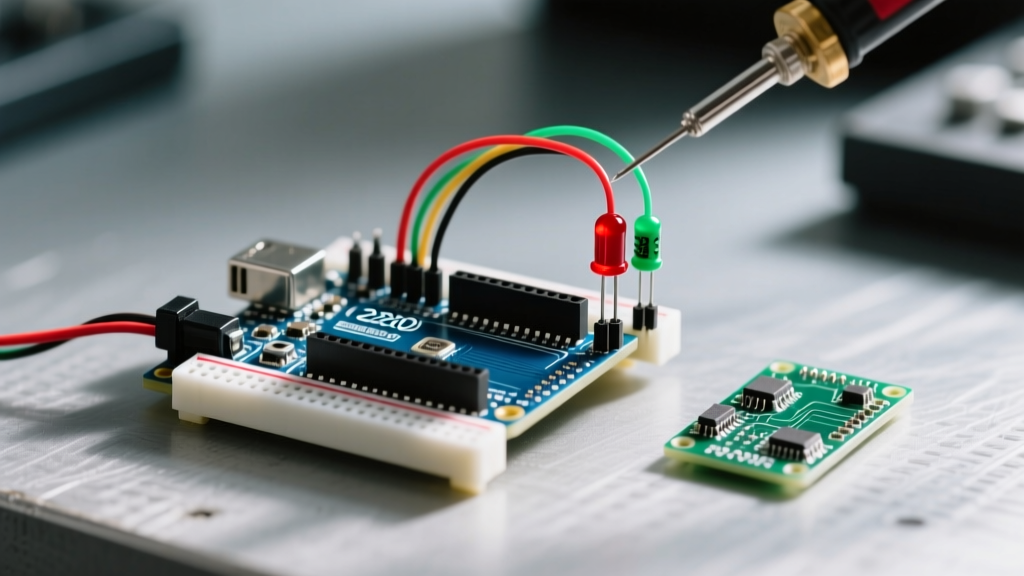
Learning how to connect LED with Arduino is universally recognized as the "Hello World" of hardware programming. However, beneath this seemingly trivial task lies a minefield of common electrical mistakes that routinely destroy microcontroller pins, cause erratic behavior, or result in frustratingly dim outputs. As makers transition from basic Arduino Uno clones to modern ESP32-S3 or Raspberry Pi Pico boards in 2026, the nuances of logic levels, forward voltage drops, and current sinking versus sourcing become critical.
This guide bypasses the basic "plug it in and upload Blink" tutorials. Instead, we approach the circuit from an Error Diagnosis perspective, equipping you with the multimeter workflows, schematic corrections, and edge-case knowledge required to troubleshoot failed LED integrations.
The Baseline Circuit and Ohm's Law Reality Check
Before diagnosing a failure, we must establish the mathematically correct baseline. A standard 5mm through-hole LED requires a current-limiting resistor. Relying on the internal pull-up resistors of an ATmega328P is a frequent beginner error that results in micro-ampere current flow, yielding a barely visible glow.
According to SparkFun's comprehensive LED guide, calculating the exact resistor requires knowing the LED's Forward Voltage ($V_f$) and your target current ($I$).
Quick Resistor Calculation Matrix
| LED Color | Typical $V_f$ | Target Current | Required Resistor (at 5V Logic) | Standard E12 Value |
|---|---|---|---|---|
| Red | 1.8V - 2.2V | 15mA | 186Ω - 213Ω | 220Ω (Red-Red-Brown) |
| Green / Yellow | 2.0V - 2.2V | 15mA | 186Ω - 200Ω | 200Ω or 220Ω |
| Blue / White | 3.0V - 3.4V | 15mA | 106Ω - 133Ω | 120Ω (Brown-Red-Brown) |
Note: Using a 10kΩ resistor (Brown-Black-Orange) instead of a 220Ω resistor is the #1 cause of "dim LED" support tickets on maker forums.
Diagnostic Matrix: Symptom to Root Cause
When your circuit fails to illuminate, use this diagnostic matrix to isolate the fault domain before rewriting your firmware.
| Observed Symptom | Probable Hardware Fault | Multimeter Test (DC Voltage) | Corrective Action |
|---|---|---|---|
| Completely Dark | Reversed polarity or open breadboard contact | Measure across LED legs. Should read $V_f$ (e.g., 2.0V). If 5V, circuit is open. | Flip LED. Check breadboard continuity. |
| Extremely Dim | Incorrect resistor value or floating ground | Measure voltage drop across resistor. If > 4V, resistance is too high. | Replace with correct E12 resistor. |
| Flickering Randomly | EMI interference or unconfigured pin state | Check pin with oscilloscope or logic analyzer. | Add pinMode(pin, OUTPUT) and 10kΩ pull-down. |
| LED Stays ON Constantly | Shorted microcontroller pin or missing GND | Measure pin voltage with code set to LOW. If > 0.5V, pin is fried. | Move to a different GPIO pin. |
Deep Dive: The "Dead Pin" Failure Mode (Overcurrent Damage)
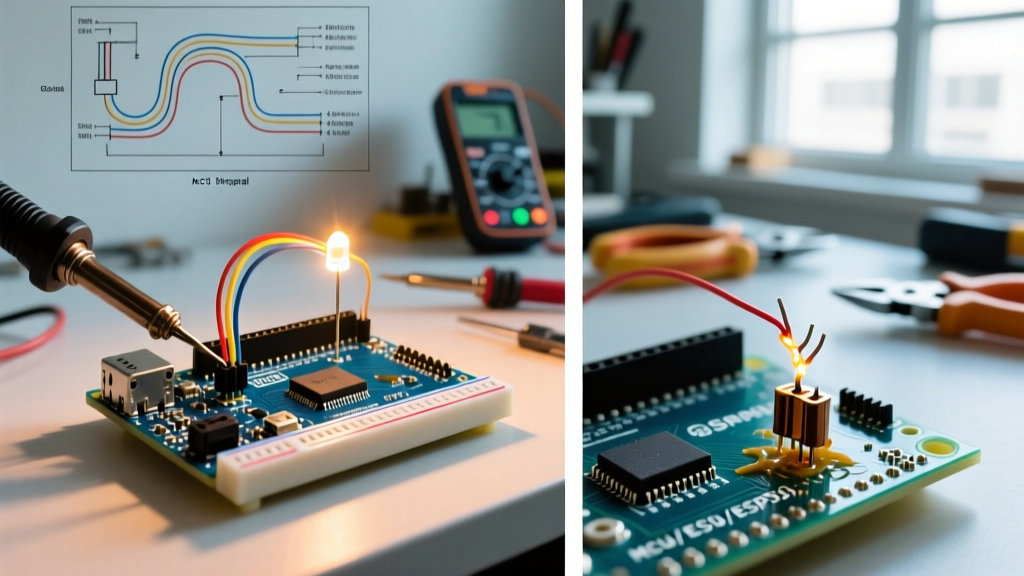
If you connected an LED directly to a digital pin without a resistor and the light flashed brilliantly for a millisecond before dying permanently, you have likely exceeded the absolute maximum ratings of the silicon.
The Microchip ATmega328P datasheet specifies an absolute maximum DC current of 40mA per I/O pin, and a total package limit of 200mA for all pins combined. However, continuous operation at 40mA accelerates electromigration and thermal degradation. Professional engineering standards dictate designing for 20mA or less per pin.
Expert Warning: Sourcing current (pin to LED to GND) and sinking current (VCC to LED to pin) behave differently on older AVR architectures. Sinking current is often preferred for 7-segment displays because the ATmega ground pins can handle slightly more aggregate current than the VCC pins, though you must still respect the 200mA total package limit.
High-Power Edge Case: 1W and 3W Cree LEDs
A common 2026 maker project involves integrating high-power illumination (like a 3W Cree XP-E2 LED requiring 700mA). You cannot connect this directly to an Arduino. Attempting to do so will instantly vaporize the microcontroller's internal bond wires.
The Fix: Use a logic-level N-Channel MOSFET like the IRLZ44N or a surface-mount AO3400. Connect the Arduino PWM pin to the MOSFET gate via a 220Ω resistor, add a 10kΩ pull-down resistor from gate to source to prevent floating-gate turn-on during microcontroller boot, and drive the high-current LED through the MOSFET's drain and source using an external 5V/12V power supply.
Logic Level Mismatches: ESP32 vs. Arduino Uno
As the industry shifts toward 3.3V logic microcontrollers like the ESP32-C3 and Raspberry Pi Pico, legacy wiring diagrams cause silent failures.
If you are researching how to connect LED with Arduino but are actually using an ESP32, you must account for the 3.3V logic high output. According to the official Espressif GPIO documentation, the ESP32 outputs a maximum of ~3.3V on a HIGH state.
If you attempt to drive a standard Blue or White LED (which requires a $V_f$ of 3.2V to 3.4V) directly from an ESP32 pin with a standard 220Ω resistor, the LED will likely remain dark or glow faintly. The voltage headroom ($3.3V - 3.2V = 0.1V$) is insufficient to push meaningful current through the resistor and the LED junction.
Solutions for 3.3V Logic Limitations
- Drop the Resistor Value: Use a 47Ω or 68Ω resistor to maximize current flow within the pin's safe limits (ESP32 pins can safely source ~20mA, though 12mA is recommended for longevity).
- Use a Lower $V_f$ LED: Switch to Red, Orange, or Yellow LEDs, which operate perfectly on 3.3V logic with standard 150Ω resistors.
- Implement a Level Shifter / Transistor: Use a BJT (like the 2N2222) or a logic-level MOSFET to switch a 5V rail, ensuring the LED receives adequate forward voltage.
Step-by-Step Multimeter Diagnosis Workflow
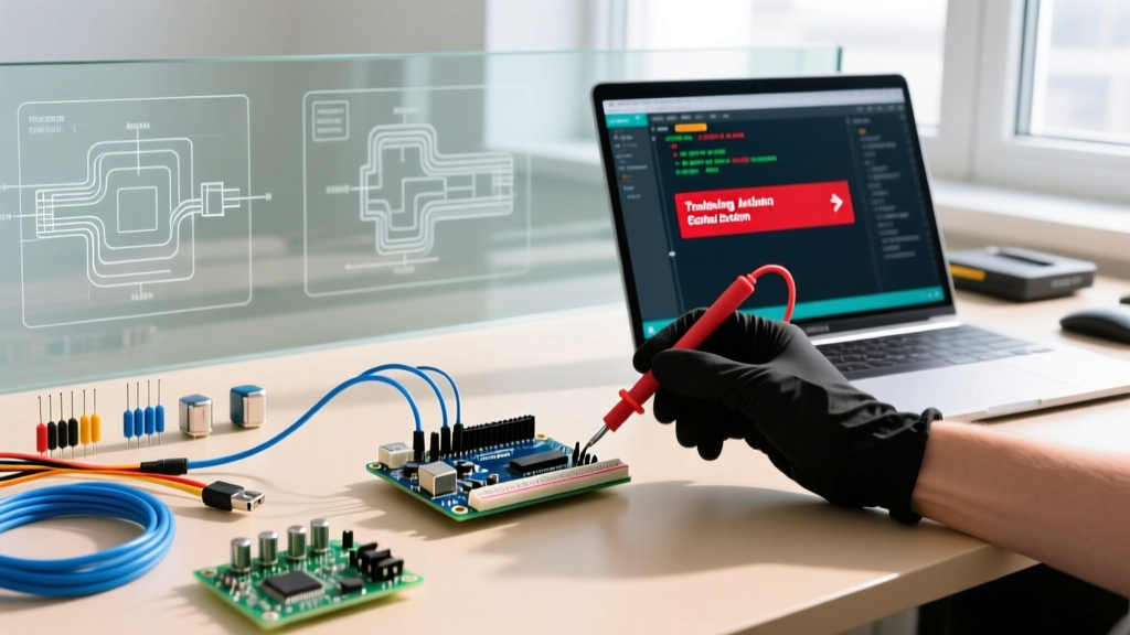
When the firmware is verified and the wiring looks correct, deploy a reliable True-RMS multimeter (such as the Fluke 117 or the budget-friendly Kaiweets KM601, typically retailing around $45 in 2026) to perform this sequential diagnostic flow:
- Verify Source Voltage: Set the multimeter to DC Voltage. Place the black probe on the Arduino GND pin and the red probe on the 5V (or 3.3V) pin. If you read 4.2V on a 5V board, your USB cable is experiencing severe voltage drop, or the onboard linear regulator is overheating. Replace the cable.
- Verify GPIO Output: Upload a sketch that sets the target pin
HIGHconstantly. Measure between the target digital pin and GND. You should read exactly the logic level voltage (5.0V or 3.3V). If you read 0V, your pin mapping in code is wrong, or the pin is physically dead. - Verify Resistor Continuity: Power down the board. Set the multimeter to Resistance (Ω). Measure across the resistor legs. A 220Ω resistor should read between 209Ω and 231Ω (accounting for 5% gold-band tolerance). If it reads OL (Open Line), the resistor is blown or not making breadboard contact.
- Verify LED Junction: Set the multimeter to the Diode Test mode (usually indicated by a diode symbol). Touch the red probe to the LED anode (long leg) and black to the cathode (flat edge). A healthy LED will light up faintly and display a voltage drop (e.g., 1.85V for red). If it reads OL in both directions, the LED is dead.
Summary: Engineering Reliability into Basic Circuits
Mastering how to connect LED with Arduino is less about memorizing a breadboard layout and more about understanding the underlying physics of semiconductor junctions and microcontroller current limits. By calculating exact resistor values, respecting 3.3V vs 5V logic thresholds, and utilizing MOSFETs for high-current loads, you transition from a hobbyist guessing at wiring to an engineer designing robust, fault-tolerant hardware systems.