
The Core Misunderstanding: PWM vs. True Analog Output
When makers first encounter the analogWrite() function in the Arduino IDE, a fundamental misconception often leads to hours of frustrating debugging. The function name implies a true Digital-to-Analog Converter (DAC) output, but on 90% of classic Arduino boards, it actually generates Pulse Width Modulation (PWM). If your analogWrite() in Arduino is failing to drive an analog sensor, producing erratic motor behavior, or compiling with errors on newer microcontrollers, you are likely fighting the hardware architecture, not the code.
Expert Insight: A standard ATmega328P-based Arduino Uno does not have a true DAC. When you call analogWrite(pin, 127), the pin is not outputting a steady 2.5V. It is rapidly toggling between 0V and 5V at a 50% duty cycle. If your target component requires a true steady DC voltage, you must add an external RC low-pass filter or use a dedicated DAC module like the MCP4725.In this diagnostic guide, we will dissect the most common hardware and software failure modes associated with analogWrite(), ranging from silent timer conflicts to the massive API shifts in the 2024-2026 ESP32 Arduino cores.
Hardware Diagnosis: Are You Using the Right Pins?
The most frequent beginner error is attempting to use analogWrite() on a digital pin that lacks a hardware PWM timer mapping. On classic AVR boards, PWM-capable pins are marked with a tilde (~) on the silkscreen. If you call analogWrite() on a non-PWM pin, the Arduino core falls back to a digital threshold: any value below 128 outputs LOW, and 128 or above outputs HIGH. This results in binary on/off behavior instead of a smooth fade or speed control.
PWM Pin Mapping & Frequency Table
| Board Model | Microcontroller | Valid PWM Pins | Default Base Frequency |
|---|---|---|---|
| Uno / Nano | ATmega328P | 3, 5, 6, 9, 10, 11 | 490 Hz (980 Hz on pins 5 & 6) |
| Mega 2560 | ATmega2560 | 2-13, 44-46 | 490 Hz (980 Hz on pins 4 & 13) |
| Zero / MKR | SAMD21 (ARM Cortex-M0+) | All digital pins except 4 | 1000 Hz |
| ESP32 DevKit | ESP32 (Xtensa LX6) | All GPIOs (via LEDC API) | 5000 Hz (Configurable) |
Source: Arduino Official Digital Pins Documentation
The Timer Conflict Matrix (The Silent Killer)
If your code compiles, the pin is correct, but the output is stuck at 0V or 5V, you have likely encountered a timer conflict. The ATmega328P relies on three internal hardware timers to generate PWM signals. When you include certain standard libraries, they hijack these timers, silently disabling analogWrite() on specific pins.
How Libraries Steal Your PWM Pins
- Timer0 (8-bit): Controls pins 5 and 6. This timer is also responsible for
millis(),delay(), andmicros(). Altering Timer0's prescaler to change PWM frequency will break all timing functions in your sketch. - Timer1 (16-bit): Controls pins 9 and 10. Conflict: The standard
Servo.hlibrary exclusively claims Timer1 to maintain the precise 50Hz pulse required by hobby servos. If you includeServo.h,analogWrite()on pins 9 and 10 will immediately cease to function. - Timer2 (8-bit): Controls pins 3 and 11. Conflict: The
tone()function uses Timer2 to generate square waves for piezo buzzers. Callingtone()will disable PWM on pins 3 and 11.
The Fix: If you need to drive a servo and a PWM motor simultaneously on an Uno, move your motor PWM to pin 5 or 6 (Timer0), or upgrade to an Arduino Mega 2560, which features six 16-bit timers and 15 independent PWM channels.
ESP32 Core v3.x: The analogWrite() Deprecation Crisis
If you have recently updated your ESP32 board definitions in 2025 or 2026, you may have noticed that sketches using analogWrite() either fail to compile or behave erratically. Historically, the ESP32 Arduino core provided a wrapper that mapped analogWrite() to the LED Control (LEDC) peripheral behind the scenes. However, with the release of Arduino ESP32 Core v3.0.0 and subsequent v3.x updates, Espressif deprecated this legacy wrapper to enforce explicit hardware configuration and prevent memory leaks.
Migrating to the LEDC API
To restore PWM functionality on the ESP32, you must abandon analogWrite() and adopt the native ledcAttach() and ledcWrite() functions. The ESP32 does not use a 0-255 duty cycle by default; it requires you to define the resolution (e.g., 8-bit to 14-bit) and frequency.
// ESP32 Core v3.x PWM Implementation
#include <Arduino.h>

const int pwmPin = 16;

void setup() {
  // Attach pin 16 to LEDC with 5000 Hz frequency and 8-bit resolution (0-255)
  ledcAttach(pwmPin, 5000, 8);
}

void loop() {
  // Fade up
  for (int duty = 0; duty <= 255; duty++) {
    ledcWrite(pwmPin, duty);
    delay(10);
  }
}
Source: Espressif Arduino ESP32 LEDC API Reference
Attempting to force the old analogWrite() syntax on modern ESP32-S3 or ESP32-C6 boards will result in compilation errors or default to digital HIGH/LOW toggling, mimicking the exact failure mode of using a non-PWM pin on an AVR board.
Multimeter vs. Oscilloscope: Measuring the Output
When diagnosing analogWrite() in Arduino, the tool you use to measure the output dictates the data you see. A common diagnostic trap is using a standard Digital Multimeter (DMM) to verify the voltage.
The DMM Averaging Trap
A standard DMM (like the $20 AstroAI or even a $150 Fluke 117) samples voltage at a relatively low rate and averages the input. If you output analogWrite(pin, 64) on a 5V Uno (a 25% duty cycle), your DMM will display roughly 1.25V. This tricks the maker into believing the pin is outputting a true analog DC voltage. However, if that signal is fed into a fast-responding component like a MOSFET gate or an audio amplifier, the component will react to the raw 490 Hz square wave, causing severe EMI noise, heating, or audio distortion.
Using a Logic Analyzer or Oscilloscope
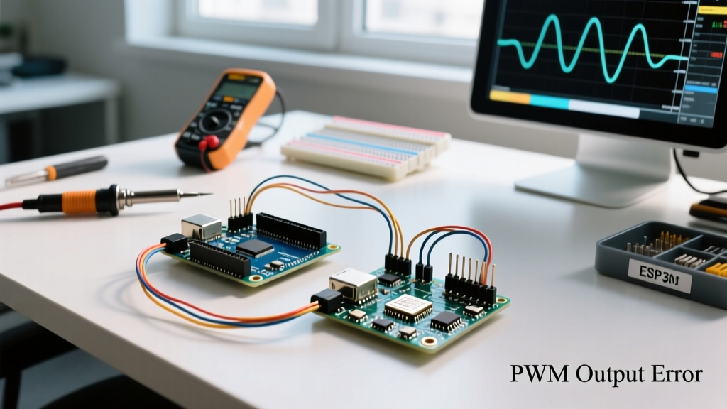
To truly diagnose PWM errors, you must visualize the waveform.
- Budget Option ($15 - $25): A generic 8-channel USB Logic Analyzer (24MHz Saleae clone) running PulseView software. This will not show voltage levels, but it will perfectly display the duty cycle and frequency, allowing you to verify if a timer conflict has flattened the signal.
- Professional Option ($400+): An entry-level oscilloscope like the Rigol DS1054Z or Siglent SDS1104X-E. This reveals the exact voltage peaks (e.g., 4.8V instead of 5.0V due to USB voltage drop) and the rise/fall times of the PWM edges, which is critical when diagnosing inductive kickback in motor driver circuits.
Quick Diagnostic Checklist for analogWrite() Failures
Before rewriting your sketch or replacing your microcontroller, run through this 5-point diagnostic checklist:
- Verify the Silkscreen: Does the pin have a
~symbol? (AVR boards only. SAMD and ESP32 boards handle this differently). - Audit Included Libraries: Are you using
Servo.h,tone(), orSoftwareSerial.h? Check the timer matrix above to ensure your target PWM pin hasn't been hijacked. - Check the Value Range: Are you passing a float or an integer greater than 255? The function expects an
intfrom 0 to 255. Passing 256 will cause an overflow, wrapping back to 0 and turning the pin off. - Verify pinMode(): While
analogWrite()technically configures the pin as an output automatically on AVR boards, explicitly callingpinMode(pin, OUTPUT)insetup()prevents edge-case initialization bugs on third-party clone boards and ARM-based MCUs. - Confirm Board Core Version: If using an ESP32, check your Boards Manager. If you are on v3.0.0 or newer, migrate your code to
ledcAttach()andledcWrite().
Conclusion
Diagnosing analogWrite() in Arduino requires looking past the simplicity of the function name. By understanding the underlying hardware timers, respecting the limitations of PWM versus true DAC, and adapting to modern API shifts in the ESP32 ecosystem, you can eliminate erratic hardware behavior. Always validate your assumptions with an oscilloscope or logic analyzer, as the microcontroller is only ever doing exactly what the silicon architecture dictates.
For further reading on AVR timer configurations, refer to the Arduino Language Reference for analogWrite.