
The Hidden Limits of a Breadboard Arduino
Building a 'breadboard Arduino' by dropping an ATmega328P-PU DIP chip onto a solderless breadboard is a rite of passage for makers. It is an excellent way to validate a concept, blink a few LEDs, and read basic analog sensors. However, as your project evolves from a weekend experiment to a permanent installation or a complex sensor node, the physical limitations of the solderless breadboard begin to cause silent, maddening failures.
In 2026, with the maker market saturated with high-speed I2C sensors, SPI-driven TFT displays, and low-power sleep modes, the breadboard is often the weakest link in your hardware stack. The primary culprits are contact resistance and parasitic capacitance. A standard solderless breadboard exhibits a contact resistance ranging from 50mΩ to over 200mΩ per junction. While negligible for powering an LED, this resistance, combined with the breadboard's inherent parasitic capacitance of 2pF to 5pF per node, creates an RC low-pass filter that destroys signal integrity.
If you are running I2C at 400kHz (Fast Mode), the degraded rise times caused by breadboard parasitics will lead to missing bytes, bus lockups, and phantom sensor readings. Similarly, high-impedance analog inputs will pick up cross-talk from adjacent digital traces. When your sketch starts throwing random I2C timeouts or your ADC readings jitter by 15-20 LSBs, it is time to migrate.
Evaluating Your Migration Path
Moving away from the breadboard Arduino does not necessarily mean jumping straight to a 4-layer SMD PCB. Below is a decision matrix to help you choose the right upgrade path based on your project's deployment environment, budget, and your current EDA (Electronic Design Automation) skills.
| Migration Path | Estimated Cost (2026) | Time to Deploy | Reliability | Best Use Case |
|---|---|---|---|---|
| Perfboard / Stripboard | $3.00 - $6.00 | 2 - 4 Hours | Medium | Permanent indoor installations, quick weekend fixes, through-hole only. |
| Pre-built Standalone (Nano/Pro Mini) | $4.50 - $9.00 | 30 Minutes | High | When you need reliability immediately without designing a custom circuit. |
| Custom 2-Layer PCB | $2.00 - $5.00 (per batch) | 1 - 2 Weeks | Very High | Product prototyping, SMD components, compact wearables, high-speed buses. |
Path 1: The Perfboard Upgrade (Weekend Migration)
If your circuit relies entirely on through-hole components and you need a permanent solution today, perfboard (prototyping board) is your best option. Products like the Adafruit Perma-Proto boards are excellent because they mimic the breadboard layout but feature plated through-holes and a solid ground plane, drastically reducing parasitic capacitance and improving high-frequency performance.
Execution Strategy for Perfboard
- Wire Selection: Abandon stranded jumper wires. Use 22 AWG or 24 AWG solid-core copper wire. Strip exactly 1/4 inch of insulation to prevent adjacent shorts.
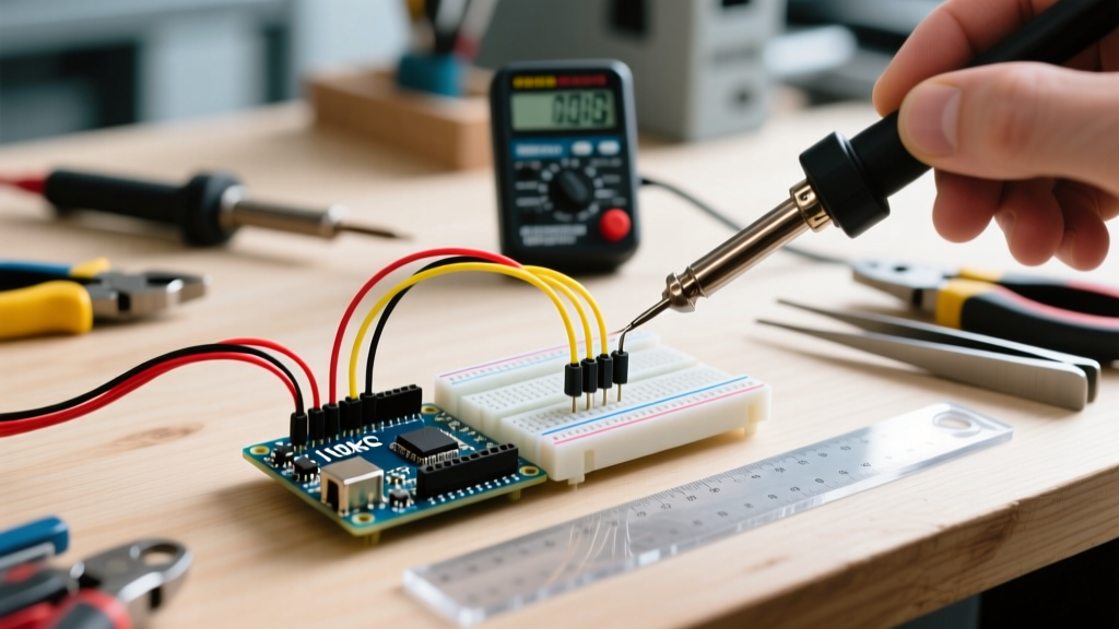
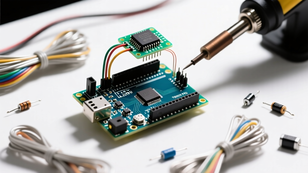
- Soldering Technique: Follow a proper through-hole soldering methodology. Heat the pad and the component lead simultaneously for 2 seconds before applying 60/40 rosin-core solder. A shiny, concave fillet indicates a solid metallurgical bond.
- Component Placement: Keep the 16MHz crystal and its 22pF load capacitors as close to the ATmega328P pins (XTAL1 and XTAL2) as physically possible. Long traces here act as antennas and can cause the microcontroller to fail to boot in electrically noisy environments.
Path 2: Custom PCB Design (The Professional Leap)
For projects requiring surface-mount devices (SMD), compact form factors, or high-speed communication, designing a custom PCB is mandatory. In 2026, the barrier to entry for custom PCBs is virtually zero. Using open-source EDA tools like KiCad 8.0 and low-cost fab houses like JLCPCB or PCBWay, you can order five 2-layer boards for roughly $2.00 to $5.00, with shipping times stabilizing to under 10 days globally.
Transitioning from DIP to TQFP
The most significant advantage of a custom PCB is the ability to abandon the bulky ATmega328P-PU (DIP-28) package. By migrating to the ATmega328P-AU (TQFP-32), you save substantial board real estate and reduce the parasitic inductance of long through-hole leads. The TQFP-32 package also exposes two additional ADC pins (ADC6 and ADC7) that are physically unavailable on the DIP version due to package limitations.
Expert Tip: When designing your PCB footprint for the TQFP-32, add a 0.1µF (100nF) decoupling capacitor on the AREF pin to ground, and ensure both VCC and AVCC have dedicated 100nF capacitors placed within 2mm of the IC pins. Skipping the AVCC decoupling is the number one cause of noisy ADC readings in custom Arduino clones.
The Minimal ATmega328P Circuit: Migration BOM
Whether you are wiring a perfboard or laying out a PCB, you must replicate the minimal support circuit required by the ATmega328P. The official Arduino IDE expects specific hardware configurations to successfully upload sketches via the serial bootloader.
| Component | Value / Spec | Purpose & Placement Notes |
|---|---|---|
| Microcontroller | ATmega328P-PU (with Optiboot) | Must be pre-flashed with the Uno bootloader if using serial upload. |
| Crystal Oscillator | 16.000 MHz (HC49/S) | Determines clock speed. Required for standard Arduino timing functions. |
| Load Capacitors | 22pF Ceramic (x2) | Connects from each crystal pin to ground. Critical for stable oscillation. |
| Reset Pull-up | 10kΩ Resistor | Connects RESET pin to VCC. Prevents floating reset and random reboots. |
| DTR Coupling Cap | 0.1µF (100nF) Ceramic | Placed between the USB-Serial DTR line and the RESET pin for auto-reset. |
| Decoupling Caps | 100nF Ceramic (x3) | Required on VCC, AVCC, and AREF pins to ground. Filters high-frequency noise. |
Common Migration Pitfalls and Edge Cases
Migrating from a breadboard Arduino to a soldered format often exposes wiring errors that the breadboard's internal bus strips were masking. Watch out for these specific failure modes:
- The Floating AREF Disaster: If you are using the internal 1.1V or 2.56V analog reference voltage in your code (
analogReference(INTERNAL)), you must never connect an external voltage to the AREF pin. On a breadboard, it is easy to accidentally leave a jumper wire connected. On a PCB, ensure AREF is only connected to a decoupling capacitor and nothing else unless you are strictly using the DEFAULT (VCC) reference. - I2C Pull-up Resistor Sizing: Breadboards often mask weak I2C pull-ups due to their high leakage and capacitance. When migrating to a clean PCB, the bus will become highly reflective if not terminated properly. For a 400kHz I2C bus running at 5V with standard trace lengths, use 2.2kΩ pull-up resistors on both SDA and SCL. The standard 10kΩ resistors found on many sensor breakout boards are too weak for fast-mode operation on longer custom traces.
- Bootloader ISP Wiring Errors: If you buy blank ATmega328P chips to save money (roughly $2.50 each in 2026 compared to $6.00 for pre-bootloaded chips), you must burn the bootloader using an ISP programmer (or a second Arduino). The most common mistake is misaligning the SPI header. Remember that the Arduino ISP sketch outputs SCK, MISO, and MOSI on pins 13, 12, and 11 respectively, which must map exactly to the target chip's hardware SPI pins.
Frequently Asked Questions
Can I run a breadboard Arduino without the 16MHz crystal?
Yes, but it requires re-flashing the bootloader. You can configure the ATmega328P to use its internal 8MHz RC oscillator by changing the fuse bits via an ISP programmer and selecting the 'Arduino Pro or Pro Mini (3.3V, 8MHz)' board profile in the IDE. This eliminates the need for the external crystal and 22pF capacitors, saving space and reducing BOM costs, but sacrifices the precision required for reliable UART serial communication at high baud rates.
Why does my migrated circuit reset when a relay switches on?
This is a classic brownout issue caused by inadequate power delivery. Breadboards have thick internal power rails that can momentarily supply high inrush currents. When you migrate to perfboard or thin PCB traces, the voltage drop across the traces when a relay coil energizes can cause the ATmega328P's VCC to dip below the Brown-Out Detection (BOD) threshold (typically 2.7V or 4.3V). To fix this, add a 100µF electrolytic bulk capacitor near the power entry point, and a flyback diode (1N4007) across the relay coil.