
PCA9685 Arduino Quick Reference & Hardware Specs
The NXP PCA9685 is an I2C-bus controlled 16-channel, 12-bit PWM controller. It is the industry standard for offloading PWM generation from microcontrollers, allowing an Arduino to control up to 16 servos or high-power LEDs using only two I2C pins. Whether you are using the official Adafruit 16-Channel PWM/Servo Shield or a generic clone board, understanding the hardware limitations and I2C protocol is critical for stable operation.
| Parameter | Specification / Limit | Notes & Best Practices |
|---|---|---|
| Logic Voltage (VCC) | 3.0V to 5.0V | Match to your MCU logic level (3.3V for ESP32, 5V for Uno). |
| Output Power (V+) | 5.0V to 10V (Max 10V) | Use 5V-6V for standard RC servos; 12V for LED strips. |
| PWM Resolution | 12-bit (4096 steps) | Provides ultra-smooth servo transitions and LED dimming. |
| Max PWM Frequency | 1526 Hz (Default: 50Hz) | 50Hz is required for standard analog RC servos. |
| I2C Base Address | 0x40 (Hex) | Configurable up to 62 unique addresses via A0-A5 pads. |
Wiring & Power Delivery FAQs
What is the difference between VCC and V+ on the terminal block?
This is the most common point of failure for beginners. The PCA9685 module separates logic power from output power:
- VCC (Logic Power): This powers the internal I2C chip and sets the I2C logic high voltage. Connect this to your Arduino's 5V pin (or 3.3V pin if using an ESP32/Raspberry Pi Pico). Do not connect high-current loads here.
- V+ (Output Power): This supplies power to the 16 output channels (the middle pins on the servo headers). Connect this to an external power supply capable of handling your load. The V+ terminal block accepts up to 10V, but standard servos require 5V to 6V.
Can I power 16 servos directly from the Arduino's 5V pin?
No. A standard Arduino Uno's onboard 5V regulator can safely supply only about 500mA to 800mA. A single standard servo (like the MG996R) can draw up to 2.5A under stall conditions. Connecting multiple servos to the Arduino's 5V rail will cause severe voltage drops, brownouts, and permanent damage to the Arduino's voltage regulator.
Pro-Tip for High-Current Builds: For a 16-servo array using MG996R or similar high-torque servos, use a dedicated 5V switching power supply rated for at least 10A to 20A (such as the Mean Well LRS-100-5). Always wire the external PSU's Ground (GND) to the PCA9685's GND terminal to establish a common logic reference.
I2C Address Configuration & Chaining
How do I change the I2C address to chain multiple boards?
The PCA9685 features six address jumper pads (A0 through A5) on the PCB. By soldering these pads closed (bridging them with solder), you alter the I2C address. The base address is 0x40. Each closed pad adds a binary value to the base address.
| Jumper Closed | Binary Offset | Hex Address | Decimal Address |
|---|---|---|---|
| None (Base) | 000000 | 0x40 | 64 |
| A0 | 000001 | 0x41 | 65 |
| A1 | 000010 | 0x42 | 66 |
| A0 + A1 | 000011 | 0x43 | 67 |
| A5 (Max single) | 100000 | 0x60 | 96 |
According to the official NXP PCA9685 datasheet, you can chain up to 62 boards on a single I2C bus, avoiding the reserved hardware addresses.
Software, Math & PWM Resolution
How do I calculate the 12-bit PWM pulse width for servos?
Unlike the Arduino analogWrite() function which uses 8-bit resolution (0-255), the PCA9685 uses 12-bit resolution (0-4095). To control a standard 50Hz RC servo, you must translate milliseconds into 12-bit steps.
- Calculate the Period: At 50Hz, one full PWM cycle is 20ms (20,000µs).
- Calculate Step Size: 20,000µs / 4096 steps = 4.8828µs per step.
- Translate Servo Pulses: A standard servo expects a pulse between 1ms (1000µs) and 2ms (2000µs).
- 1ms pulse = 1000 / 4.8828 ≈ 205 steps (0 degrees)
- 1.5ms pulse = 1500 / 4.8828 ≈ 307 steps (90 degrees)
- 2ms pulse = 2000 / 4.8828 ≈ 410 steps (180 degrees)
When using the Adafruit PWM Servo Driver Library, you pass these step values directly into the setPWM(channel, on_step, off_step) function. Set on_step to 0, and off_step to your calculated pulse length (e.g., 205 to 410).
What is the OE (Output Enable) pin used for?
The OE pin is an active-low hardware kill switch. If you pull the OE pin to GND, the PWM outputs are active. If you pull OE HIGH (to 5V), all 16 outputs are immediately disabled (high-impedance state). This is highly useful for emergency stop circuits in robotics; wire the OE pin to a physical E-Stop button or a secondary safety microcontroller to instantly cut power to the servo signal lines without needing to send I2C commands.
Troubleshooting Common Edge Cases
Why are my servos jittering or twitching randomly?
Servo jitter is almost always a power or signal integrity issue, not a code bug. Check these three failure modes:
- Power Supply Ripple: Switching power supplies can introduce high-frequency noise. Solder a 1000µF 10V electrolytic capacitor directly across the V+ and GND screw terminals on the PCA9685 board to smooth out voltage transients during servo startup spikes.
- Missing Common Ground: The GND of your external servo power supply must be connected to the GND of the PCA9685 and the Arduino. Without a shared ground reference, the I2C logic signals will float, causing erratic PWM generation.
- I2C Bus Capacitance: If you are using long wires between the Arduino and the PCA9685, the wire capacitance can distort the I2C square wave. Keep I2C SDA/SCL wires under 30cm, or use an I2C bus extender (like the P82B715) for longer runs.
The I2C Scanner doesn't find the board. What's wrong?
If the standard Arduino Wire library I2C scanner returns no devices, verify the following:
- Logic Level Mismatch: If using a 3.3V MCU (like the ESP32-S3), ensure the PCA9685 VCC pin is connected to 3.3V. Powering VCC with 5V while the MCU outputs 3.3V I2C signals can result in the PCA9685 failing to recognize the logic HIGH threshold.
- Pull-Up Resistor Overload: Official Adafruit boards include 10kΩ pull-up resistors on the SDA and SCL lines. If you chain more than three boards together, the parallel resistance drops significantly, potentially pulling the I2C lines too low. Cut the pull-up jumper traces on the slave boards, leaving them only on the master board.
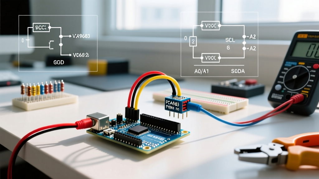
- Clone Board Defects: Generic $3 clone boards often suffer from cold solder joints on the I2C header pins or missing the onboard 5V-to-3.3V logic regulator. Inspect the header pins with a multimeter for continuity.
Can I use the PCA9685 to dim high-power LED strips?
Yes, but with caveats. The PCA9685 outputs are open-drain N-channel MOSFETs. They can sink current but cannot source it. To drive 12V LED strips, connect the LED strip's 12V+ to your power supply, and connect the LED strip's GND to the PCA9685 output channel pins. However, the onboard MOSFETs are typically rated for only 25mA per channel. For high-power LEDs, you must use the PCA9685 output pins to trigger external logic-level MOSFETs (like the IRLZ44N) or dedicated LED driver ICs.