
Active vs. Passive: Understanding the Piezo Hardware
When integrating audio feedback into microcontroller projects, makers generally choose between two components: the active buzzer and the passive buzzer. While they look nearly identical on the outside—often housed in the same black plastic casing with a small hole for sound emission—their internal electronics dictate entirely different wiring and coding strategies. For a passive buzzer Arduino setup, understanding these differences is the first step toward generating custom pitches, melodies, and alert tones.
| Feature | Active Buzzer (e.g., KY-012) | Passive Buzzer (e.g., KY-006) |
|---|---|---|
| Internal Oscillator | Built-in (Requires only DC power) | None (Requires external square wave) |
| Pitch Control | Fixed (Usually ~2.7 kHz) | Variable (Depends on input frequency) |
| Arduino Control | Digital HIGH/LOW | PWM / tone() function |
| Typical Cost (2026) | $0.60 - $1.10 | $0.45 - $0.85 |
An active buzzer contains an internal oscillating circuit. You simply apply a DC voltage (e.g., 5V), and it produces a loud, fixed-pitch beep. A passive buzzer, however, lacks this internal oscillator. It relies entirely on the microcontroller to provide an alternating current (AC) signal—specifically, a square wave at the desired audio frequency. If you apply a static 5V DC signal to a passive buzzer, it will merely emit a single, faint 'click' and then fall silent.
Step-by-Step Wiring Guide & Circuit Protection
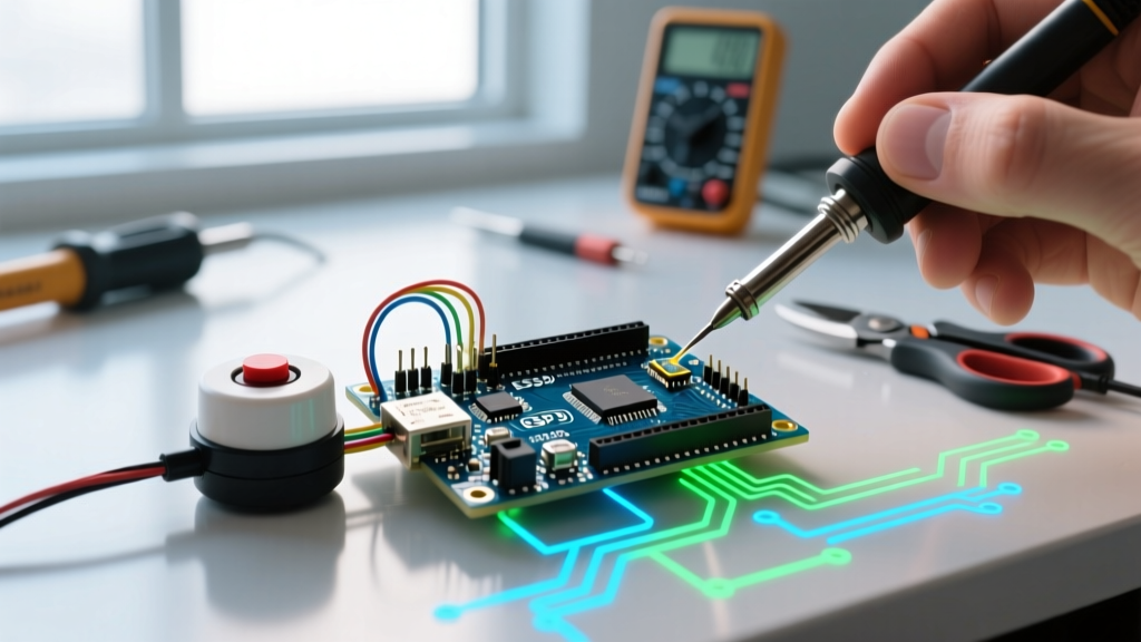
Wiring a passive buzzer to an Arduino Uno R3 (or any ATmega328P-based board) seems straightforward: connect one pin to a digital GPIO and the other to GND. However, skipping a crucial protective component can lead to long-term microcontroller degradation.
The Inrush Current Problem
A piezoelectric buzzer acts electrically like a capacitor (typically between 1 nF and 5 nF for standard 12mm discs). When the Arduino GPIO pin transitions from LOW (0V) to HIGH (5V), it must rapidly charge this capacitive load. According to the formula I = C(dv/dt), a near-instantaneous voltage change results in a massive inrush current spike. This spike can easily exceed the ATmega328P's absolute maximum rating of 40mA per pin, potentially damaging the silicon over time.
The Proper Wiring Sequence
- Identify the Pins: If your passive buzzer module (like the KY-006) has three pins (GND, VCC, I/O), the I/O pin is the signal input. If you are using a raw, bare piezo disc, polarity generally does not matter for audio generation, though the red wire is conventionally positive.
- Add a Current-Limiting Resistor: Place a 100Ω to 330Ω resistor in series between the Arduino digital pin and the buzzer's positive terminal. This limits the inrush current to a safe ~15mA while still allowing the square wave to drive the piezo disc effectively.
- Connect Ground: Wire the buzzer's negative terminal directly to the Arduino's GND pin.
- Choose the Right GPIO: Use Pin 8 or Pin 9 for this tutorial. Avoid Pins 3 and 11 if you are using an older ATmega328P board and also need PWM for LEDs or motors (explained below).
Mastering the Arduino tone() Function
To drive the passive buzzer, we use the built-in Arduino tone() function. This function generates a 50% duty cycle square wave on the specified pin, which physically vibrates the piezo ceramic at the exact frequency you request.
The syntax is simple: tone(pin, frequency, duration);
- pin: The digital GPIO pin number.
- frequency: The pitch in Hertz (Hz). The ATmega328P supports 31 Hz to 65,535 Hz, though human hearing tops out around 20,000 Hz, and cheap piezo discs resonate loudest between 2,000 Hz and 4,000 Hz.
- duration: (Optional) How long the tone should play in milliseconds. If omitted, the tone plays indefinitely until
noTone(pin)is called.
⚠️ Hardware Timer Conflict Warning: On ATmega328P-based boards (like the Uno R3), thetone()function relies on the chip's internal Timer 2. Consequently, callingtone()will disable PWM (analogWrite()) functionality on Pins 3 and 11. Note that newer boards released in the mid-2020s, such as the Uno R4 (Renesas RA4M1 architecture), handle timer allocation dynamically, largely eliminating this specific PWM conflict, though consuming a hardware timer resource is still required.
Code Example 1: The Frequency Sweep
The best way to test a passive buzzer Arduino circuit and find its mechanical resonant frequency (the pitch where it sounds the loudest) is to run a frequency sweep. Upload the following sketch to your board:
// Passive Buzzer Frequency Sweep
const int buzzerPin = 8;

void setup() {
  pinMode(buzzerPin, OUTPUT);
}

void loop() {
  // Sweep from 100 Hz to 5000 Hz
  for (int freq = 100; freq <= 5000; freq += 50) {
    tone(buzzerPin, freq, 20); // Play for 20ms
    delay(25); // Brief pause between steps
  }

  // Silence for 2 seconds before repeating
  noTone(buzzerPin);
  delay(2000);
}
Listen closely as the code runs. You will notice the volume swells dramatically around the 2,700 Hz to 3,000 Hz mark. This is the physical resonant frequency of the 12mm piezo disc. Designing your alert tones around this specific frequency ensures maximum acoustic output without requiring an external amplifier.
Code Example 2: Playing a Melody
Because you control the exact frequency, you can map musical notes to their corresponding Hertz values. The official Arduino Tone Melody Tutorial outlines how to use arrays to sequence notes. Below is a streamlined implementation using a custom note map.
#define NOTE_C4  262
#define NOTE_D4  294
#define NOTE_E4  330
#define NOTE_G4  392
#define NOTE_A4  440

const int buzzerPin = 8;

// Melody notes
int melody[] = {
  NOTE_E4, NOTE_D4, NOTE_C4, NOTE_D4, NOTE_E4, NOTE_E4, NOTE_E4
};

// Note durations: 4 = quarter note, 8 = eighth note
int durations[] = {
  4, 4, 4, 4, 4, 4, 2
};

void setup() {
  int totalNotes = sizeof(melody) / sizeof(int);

  for (int thisNote = 0; thisNote < totalNotes; thisNote++) {
    // Calculate duration in ms (1000ms / note type)
    int noteDuration = 1000 / durations[thisNote];
    tone(buzzerPin, melody[thisNote], noteDuration);

    // Pause between notes (add 30% for distinct separation)
    int pause = noteDuration * 1.30;
    delay(pause);

    // Stop the tone playing before the next begins
    noTone(buzzerPin);
  }
}

void loop() {
  // Melody plays only once on boot
}
Troubleshooting Common Edge Cases
Even with a straightforward component like a piezo disc, makers frequently encounter hardware and software quirks. Refer to this diagnostic matrix if your circuit misbehaves.
1. The Buzzer Only 'Clicks' Once
Cause: You are using digitalWrite(pin, HIGH) instead of tone().
Solution: A passive buzzer requires an alternating signal to vibrate continuously. A static HIGH signal merely charges the piezo capacitor once, resulting in a single physical click. Switch to the tone() function.
2. The Sound is Exceptionally Quiet or Distorted
Cause 1: You are driving the buzzer at a frequency far outside its mechanical resonance (e.g., 200 Hz or 15,000 Hz).
Cause 2: The buzzer is mounted flat against a breadboard or enclosed in a tight, unported 3D-printed case, which stifles the acoustic wave.
Solution: Keep alert tones between 2 kHz and 4 kHz. If using an enclosure, ensure the buzzer's emission hole aligns perfectly with a drilled port in the casing, and seal the edges with hot glue to prevent acoustic phase cancellation.
3. The Buzzer Hums Faintly When Supposed to be Off
Cause: Floating GPIO pins or electrical noise from adjacent motor drivers.
Solution: Ensure you explicitly call noTone(buzzerPin) when audio should stop. Additionally, if you are driving inductive loads (like relays or DC motors) on the same power rail, add a 100µF decoupling capacitor across the buzzer's power rails to filter out high-frequency voltage ripple.
Advanced Integration: Non-Blocking Audio
While the tone() function is excellent for beginners, it is inherently blocking if you use the duration parameter combined with delay(). For complex 2026 IoT dashboards or robotics projects where the microcontroller must simultaneously read LiDAR sensors and drive stepper motors, blocking delays are unacceptable. For advanced non-blocking audio generation, consider utilizing hardware timer interrupts or migrating to the ESP32 platform, which features a dedicated LEDC (LED Control) peripheral capable of generating high-resolution square waves in the background without consuming the main CPU threads.
By mastering the physics of the piezo disc, protecting your GPIO pins with proper current-limiting resistors, and understanding the underlying hardware timers, you transform a $0.50 component into a highly reliable, precision audio feedback system for any embedded project.