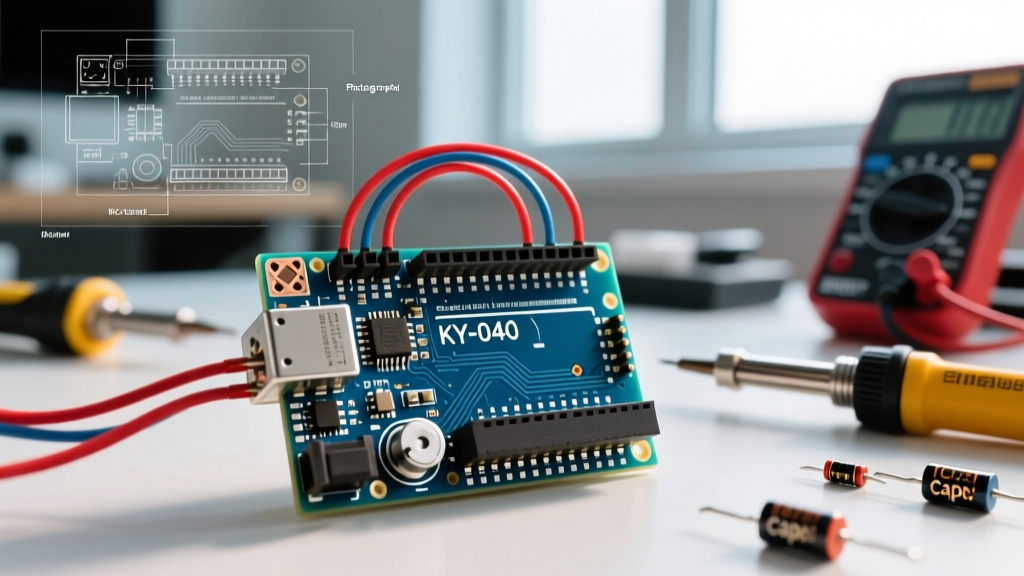
The Core Silicon: Understanding the Microcontroller Unit
When beginners search for how does a arduino work, they are usually looking at the blue or green PCB and wondering how lines of C++ code translate into physical electrical signals. At its heart, a classic Arduino Uno R3 is a development board built around a specific microcontroller unit (MCU): the Microchip (formerly Atmel) ATmega328P-PU. This is an 8-bit RISC (Reduced Instruction Set Computer) microcontroller utilizing a Harvard architecture, meaning it uses separate memory spaces and buses for program instructions and data.
To understand the execution flow, you must understand the three distinct memory partitions inside the ATmega328P:
- Flash Memory (32 KB): Non-volatile storage where your compiled sketch (and the bootloader) lives. It retains data when power is removed. Rated for 10,000 write/erase cycles.
- SRAM (2 KB): Volatile memory used for dynamic variables, the stack, and the heap during runtime. If you declare too many large arrays, you will cause a stack collision and crash the MCU.
- EEPROM (1 KB): Non-volatile memory used for storing calibration data or settings that must survive a reboot. Rated for 100,000 write/erase cycles.
Step-by-Step: The Bootloader and Execution Cycle
A raw ATmega328P chip from the factory does not know how to accept code over a USB cable. It requires a bootloader—a small program residing in the highest 512 bytes of the Flash memory. The standard bootloader for the Uno R3 is Optiboot.
The Upload Sequence Explained
- Compilation: The Arduino IDE uses the AVR-GCC compiler to translate your C++ sketch into machine code, outputting a
.hexfile. - USB-to-Serial Conversion: The Uno R3 features a secondary chip (the ATmega16U2) that acts as a USB-to-Serial bridge, converting USB packets from your PC into UART TX/RX signals.
- The DTR Reset Trick: When you click 'Upload', the PC toggles the DTR (Data Terminal Ready) line. This pulls the RESET pin of the ATmega328P LOW via a 0.1µF capacitor, forcing the MCU to reboot.
- Bootloader Execution: Upon reset, the hardware fuses tell the MCU to jump to the bootloader address. Optiboot wakes up, listens on the UART pins for a specific handshake protocol (STK500v1) for roughly 500 milliseconds.
- Flashing: If the handshake is detected, Optiboot uses the MCU's Self-Programming Memory (SPM) instructions to erase and write the new
.hexfile into the lower Flash memory. - Execution: Once flashing is complete, or if no handshake is detected after the timeout, the bootloader jumps to address
0x0000, and your application code begins executing at 16 MHz.
Hardware Peripherals: ADC, PWM, and GPIO
The true power of the MCU lies in its hardware peripherals, which operate independently of the CPU core.
Analog-to-Digital Conversion (ADC)
The ATmega328P features a 6-channel, 10-bit Successive Approximation Register (SAR) ADC. It maps the 0-5V analog input to integer values between 0 and 1023.
Expert Insight: The ADC requires its own clock. By default, the Arduino core sets the ADC prescaler to 128. With a 16 MHz system clock, this yields a 125 kHz ADC clock. Since a single conversion takes 13 ADC clock cycles, the maximum sampling rate is roughly 9,615 Hz. If you need faster sampling for audio processing, you can manually lower the prescaler to 16 (yielding a 1 MHz ADC clock and ~76 kHz sampling), though you will lose roughly 1 bit of effective resolution due to noise.
Pulse Width Modulation (PWM) and Timers
Pins marked with a tilde (~) are connected to hardware timers (Timer0, Timer1, and Timer2). These timers increment hardware counters and toggle the pin state when a match occurs. The default analogWrite() function uses Fast PWM mode at approximately 490 Hz (980 Hz on pins 5 and 6). This is sufficient for dimming LEDs but too slow for driving high-frequency switching power supplies or audio amplifiers.
Quick Reference Matrix: Classic vs. Modern Arduino Boards
As of 2026, the market offers several variations of the standard form factor. Here is how the legacy AVR boards compare to modern ARM/Renesas alternatives.
| Feature | Uno R3 (Classic) | Uno R4 Minima | Nano Every |
|---|---|---|---|
| MCU | ATmega328P (AVR) | Renesas RA4M1 (ARM Cortex-M4) | ATmega4809 (AVR) |
| Architecture | 8-bit | 32-bit | 8-bit |
| Clock Speed | 16 MHz | 48 MHz | 20 MHz |
| ADC Resolution | 10-bit | 14-bit | 10-bit (11-bit via oversampling) |
| Typical Price (2026) | $9 (Clone) / $27 (Genuine) | $22.50 (Genuine) | $12 (Clone) / $20 (Genuine) |
| Native USB HID | No (Requires 16U2 bridge) | Yes | No (Requires bridge) |
Power Delivery and Clock Sources
An Arduino requires a stable 5V logic level and a precise clock signal to execute instructions sequentially.
- The Clock: The Uno R3 uses an external 16 MHz quartz crystal oscillator paired with two 22pF load capacitors. This provides high accuracy (±30 ppm), which is critical for UART baud rate timing. Without this crystal, the MCU would fall back to its internal 8 MHz RC oscillator, which drifts heavily with temperature changes and causes serial communication failures.
- Voltage Regulation: When powered via the barrel jack (recommended 7V to 12V), the board uses an NCP1117ST50T3G linear dropout (LDO) regulator to drop the voltage to 5V. Warning: Because it is a linear regulator, the excess voltage is burned off as heat. If you supply 12V and draw 200mA from the 5V pin, the LDO must dissipate (12V - 5V) * 0.2A = 1.4 Watts. Without a heatsink, the LDO will trigger its internal thermal shutdown.
Critical Arduino Hardware FAQs
Q: What exactly happens if I pull 50mA from a single I/O pin?
A: The absolute maximum rating per I/O pin on the ATmega328P datasheet is 40mA, but the recommended operating condition is 20mA. If you pull 50mA, two things occur. First, the internal resistance of the silicon trace causes a voltage droop; your 'HIGH' pin might drop from 5V down to 3.8V, which can cause logic errors in connected ICs. Second, you risk latch-up or electromigration, where the physical aluminum bond wires inside the DIP package degrade or fuse open, permanently destroying that specific port register.
Q: Can I exceed the 200mA total VCC/GND limit?
A: No. The sum of all current sourced or sunk across all I/O pins, plus the VCC and GND pins, must not exceed 200mA. Exceeding this limit causes thermal runaway in the silicon substrate. If you need to drive high-current loads like LED strips or DC motors, you must use external logic-level MOSFETs (like the IRLZ44N) or motor driver ICs (like the L298N or DRV8833), using the Arduino only to switch the gate signals.
Q: How do I2C pull-up resistors factor into the hardware design?
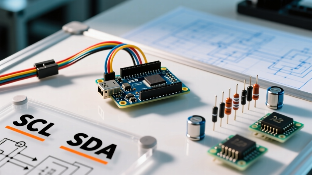
A: The I2C bus uses open-drain outputs. The MCU can pull the SDA and SCL lines LOW, but it cannot drive them HIGH. It relies on external pull-up resistors to bring the line back to VCC. The official Arduino Uno R3 documentation notes that the board does not include built-in I2C pull-ups. If you connect multiple I2C sensors and the bus becomes unstable or hangs, you typically need to add 4.7kΩ pull-up resistors to the 5V line to ensure fast enough rise times at the 400 kHz Fast Mode frequency.
Q: What is the 'Bare Bones' Arduino configuration?
A: You do not need the entire blue PCB to run Arduino code. A minimal 'bare bones' circuit requires only the ATmega328P-PU chip, a 16 MHz crystal, two 22pF capacitors, a 10kΩ pull-up resistor on the RESET pin, and a 0.1µF decoupling capacitor across the VCC and GND pins. This configuration costs under $3.00 in bulk components and is the standard way to transition from a breadboard prototype to a custom manufactured PCB.
Q: Why does my sketch freeze when using the String class?
A: The ATmega328P only has 2,048 bytes of SRAM. The C++ String object dynamically allocates memory on the heap. Frequent concatenation causes memory fragmentation. Eventually, the heap collides with the stack, resulting in a silent, unrecoverable crash. Expert embedded developers avoid the String class entirely, opting instead for fixed-size character arrays (char[]) and standard C library functions like snprintf() to manage memory deterministically.