
Rethinking the Arduino Wireless Control Pipeline
When building remote sensors, motorized actuators, or smart home nodes, mastering arduino wireless control is the difference between a weekend project and a multi-week debugging nightmare. Most makers approach wireless integration as an afterthought, bolting on an RF module only to face intermittent packet loss, power brownouts, and the dreaded "walk of shame" to plug the device back into a USB cable for every minor code tweak.
Workflow optimization in the RF space isn't just about writing cleaner code; it is about structuring your hardware selection, power delivery, and deployment pipeline to eliminate physical and logical friction. In 2026, with the proliferation of low-cost dual-core microcontrollers and mature IoT protocols, there is zero excuse for tethered debugging or unstable raw RF links. This guide breaks down a highly optimized, professional-grade workflow for Arduino wireless control, saving you dozens of hours on your next deployment.
The Hardware Decision Matrix: Stop Guessing, Start Selecting
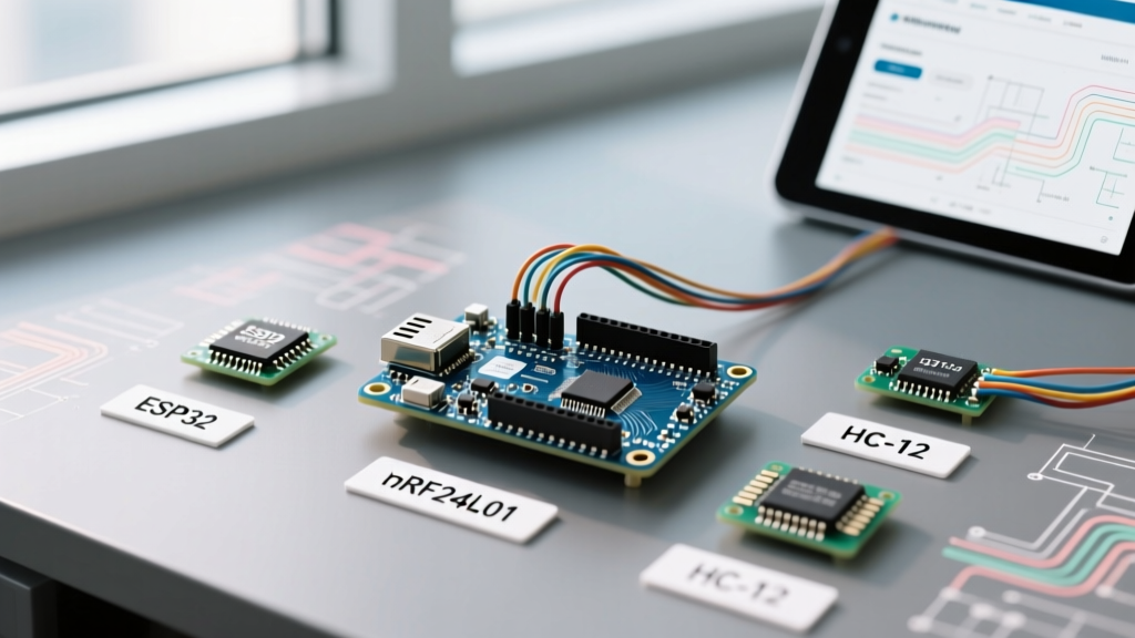
The first point of workflow failure is selecting the wrong transceiver for the environmental constraints. Choosing an nRF24L01 for a whole-home mesh, or an ESP32 for a low-power remote soil sensor, guarantees architectural rework. Use the matrix below to align your hardware with your project's actual requirements.
| Module / MCU | Approx. Cost (2026) | Protocol / Band | Real-World Range | Workflow Friction Level | Best Use Case |
|---|---|---|---|---|---|
| ESP32-WROOM-32U | $4.50 - $6.00 | Wi-Fi 4 / BLE 4.2 (2.4GHz) | 50m (Indoor) / 150m (Outdoor) | Low (Native IP stack, OTA ready) | High-bandwidth IP control, MQTT nodes, camera integration. |
| nRF24L01+ (PA+LNA) | $3.50 - $5.00 | Proprietary ShockBurst (2.4GHz) | 80m (Indoor) / 800m (LOS) | High (Requires custom gateway, strict power needs) | Low-latency RC vehicles, localized sensor meshes without Wi-Fi. |
| HC-12 (SI4463) | $5.50 - $7.00 | UART Transparent (433MHz) | 100m (Indoor) / 1.5km (LOS) | Very Low (Serial passthrough, no complex libraries) | Long-range telemetry, simple point-to-point serial bridges. |
| SX1278 (LoRa) | $8.00 - $11.00 | LoRa (433/868/915MHz) | 2km (Urban) / 15km (Rural) | Medium (Requires LoRaWAN gateway or point-to-point setup) | Agricultural sensors, remote environmental monitoring. |
Eliminating the #1 Workflow Killer: RF Power Brownouts
If you are using legacy Arduino boards (like the Uno R3 or Nano) with nRF24L01+ modules, you have likely encountered the "ghost in the machine" symptom: the radio initializes perfectly, but fails sporadically during transmission. This is almost never a code issue; it is a power delivery failure.
The 115mA Peak Current Trap
The nRF24L01+ module requires a strict 3.3V supply. During peak transmission (especially with PA/LNA amplifier variants), the module can draw up to 115mA to 120mA in microsecond bursts. The onboard 3.3V LDO regulator on most clone Arduino Nanos is rated for a mere 50mA to 150mA total, and often lacks adequate heat dissipation. When the radio requests peak current, the voltage sags below 3.0V, causing the module's internal state machine to reset mid-packet.
The Optimized Power Workflow
Stop wasting hours rewriting SPI initialization code. Implement this hardware fix on day one:
- Stage 1 (Quick Fix): Solder a 100µF electrolytic capacitor directly across the VCC and GND pins on the nRF24L01 module. This acts as a local energy reservoir to handle microsecond current spikes.
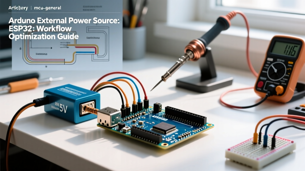
- Stage 2 (Production Fix): Bypass the Arduino's onboard regulator entirely. Use a dedicated AMS1117-3.3V buck converter module powered directly from the Arduino's 5V pin. According to the Texas Instruments AMS1117 datasheet, this configuration comfortably handles up to 1A of continuous current with excellent transient response, completely eliminating RF brownouts.
Ditching the USB Cable: Implementing an OTA-First Pipeline
The most significant bottleneck in any arduino wireless control project is the physical iteration loop: modify code, compile, walk to the device, plug in USB, upload, unplug, power via battery, and test. This physical tethering destroys workflow momentum.
Transitioning to Over-The-Air (OTA) Updates
If your project utilizes an ESP32 or an ESP8266, Over-The-Air (OTA) programming must be integrated into your base boilerplate before you write a single line of application logic. By utilizing the ArduinoOTA library, you can push compiled binaries directly over your local Wi-Fi network via the Arduino IDE's "Network Ports" menu.
As detailed in comprehensive guides like those on Random Nerd Tutorials, setting up OTA requires less than 15 lines of code in your setup() and loop() functions. The workflow optimization here is massive: a 10-iteration debugging day drops from 2.5 hours of physical cable management to roughly 4 minutes of wireless compilation pushes. Always allocate a dedicated 1.5MB partition scheme in the ESP32 board manager to ensure sufficient space for the OTA staging partition.
State Management: Why MQTT Beats HTTP for Wireless Control
When designing the communication layer for wireless actuators (like relays, stepper motors, or dimmers), many beginners default to hosting a RESTful HTTP server on the microcontroller and polling it via a web dashboard. This is an anti-pattern that leads to bloated code, high latency, and rapid battery drain.
The Publish/Subscribe Advantage
Optimize your data pipeline by adopting MQTT (Message Queuing Telemetry Transport). Using the lightweight PubSubClient library, your Arduino connects to a central broker (like Mosquitto running on a Raspberry Pi or a cloud service like HiveMQ) and simply subscribes to a control topic.
Expert Workflow Tip: When configuring MQTT for critical wireless control (e.g., garage doors or emergency shutoff valves), always set the Quality of Service (QoS) level to 1. QoS 0 is "fire and forget" and will drop packets in noisy 2.4GHz RF environments. QoS 1 guarantees "at least once" delivery, requiring a slight overhead in handshake acknowledgments but ensuring your actuator actually receives the command.
Antenna Orientation and RF Multipath Fading
A frequently overlooked aspect of wireless control workflow is the physical deployment environment. 2.4GHz signals (used by Wi-Fi, BLE, and nRF24L01) are highly susceptible to multipath fading—where signals bounce off walls and metal surfaces, arriving at the receiver out of phase and canceling each other out.
The Optimization: Never assume code is broken when a link drops at a specific distance. During the prototyping phase, mandate orthogonal antenna placement. If your base station antenna is oriented vertically, orient your remote node's antenna horizontally. While this introduces a theoretical 3dB polarization mismatch loss, it drastically reduces the probability of simultaneous multipath nulls on both axes, resulting in a vastly more stable link budget in indoor environments.
The 4-Stage RF Isolation Debugging Protocol
When your arduino wireless control link inevitably fails, do not rewrite your entire sketch. Follow this strict, isolated debugging pipeline to identify the exact point of failure within minutes:
- Stage 1: Local Loopback Validation. Disconnect the RF module. Hardcode the payload variables in your sketch and print them to the Serial Monitor. Verify your sensor logic and data structuring are flawless before introducing wireless variables.
- Stage 2: Wired SPI/UART Verification. If using SPI (nRF24L01), use a logic analyzer or an oscilloscope to probe the MOSI and SCK pins during initialization. Ensure your wiring isn't suffering from parasitic capacitance or loose Dupont connections.
- Stage 3: Line-of-Sight (LOS) Ping Test. Power both nodes via independent USB power banks. Place them 2 meters apart with clear LOS. Send a basic 1-byte heartbeat ping. If this fails, your issue is addressing or library configuration (e.g., mismatched datarates or pipe addresses).
- Stage 4: Payload Stress & Environmental Testing. Once LOS is stable, introduce your full payload structure and move the nodes into their final physical locations. Monitor the RSSI (Received Signal Strength Indicator) and packet drop rate. If drops exceed 2%, revisit your antenna orientation or switch to a lower datarate (e.g., dropping nRF24L01 from 2Mbps to 250kbps) to increase receiver sensitivity.
Conclusion
Optimizing your arduino wireless control workflow requires shifting your mindset from "making it work once" to "engineering for reliable iteration." By selecting the correct transceiver matrix, over-engineering your 3.3V power delivery, implementing OTA updates from day one, and leveraging MQTT for state management, you transform wireless prototyping from a frustrating gamble into a predictable, highly efficient engineering process.