
The '12C' Phenomenon: Decoding the I2C Bus
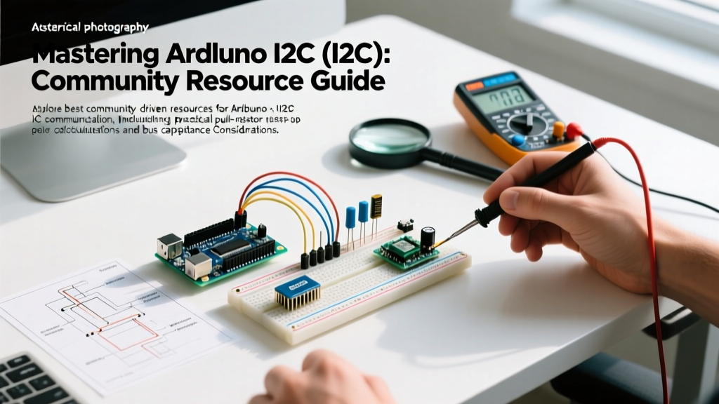
Search engines and forum newcomers frequently query Arduino 12c due to the visual similarity between the capital letter 'I' and the number '1'. In the maker and engineering communities, we recognize this as the I2C (Inter-Integrated Circuit) protocol. Originally developed by Philips (now NXP) in the 1980s, I2C remains the undisputed backbone of low-speed peripheral communication in modern microcontroller ecosystems.
Whether you are interfacing a BME280 environmental sensor, driving an SSD1306 OLED display, or networking multiple microcontrollers, mastering this two-wire synchronous bus is non-negotiable. This 2026 community resource roundup curates the most vital software libraries, hardware debugging tools, and electrical design matrices you need to conquer I2C bus failures, address collisions, and signal integrity issues.
Software Ecosystem: Beyond the Default Wire Library
The native Arduino Wire library is the starting point for 90% of makers, but it harbors legacy limitations that frequently cause headaches in complex projects. The community has developed robust alternatives and diagnostic scripts to bridge these gaps.
1. The Classic I2C Scanner Sketch
Before writing a single line of application logic, the community mandates running an I2C Scanner. This simple script iterates through all 127 possible 7-bit addresses, listening for an ACKnowledge (ACK) bit. It is the fastest way to verify wiring, confirm logic levels, and identify the hexadecimal address of unmarked Chinese breakout boards.
2. Adafruit BusIO (Modern Abstraction)
For developers writing custom libraries, the Arduino Wire reference shows that handling I2C transactions manually involves tedious buffer management. Adafruit BusIO abstracts the transport layer, allowing library authors to write code that seamlessly supports both I2C and SPI without duplicating logic. It also handles the nuances of different core architectures (AVR vs. ARM vs. ESP32) regarding buffer sizes.
3. Buffer Size Limitations (The 32-Byte Trap)
A frequent source of forum complaints is truncated data. On legacy 8-bit AVR boards (like the Uno R3), the Wire library enforces a strict 32-byte hardware buffer. If a sensor returns a 64-byte data burst, the excess is silently dropped. Modern 32-bit cores (SAMD21, RP2040, ESP32-S3) have expanded this to 256 bytes or more, but cross-platform code must implement chunked reading loops to remain universally compatible.
Hardware Debugging: 2026 Bench Staples
When the software scanner returns zero devices, the issue is physical. Oscilloscopes are useful, but dedicated logic analyzers decode the I2C state machine (Start, Stop, ACK, NACK) in real-time.
- Saleae Logic Pro 8 ($399): The industry gold standard. Its software automatically decodes I2C packets, highlighting NACKs in red. Essential for professional firmware engineers debugging timing violations.
- Digilent Analog Discovery 3 ($299): A community favorite for its mixed-signal capabilities. It allows you to simultaneously view the analog voltage sag on the SDA line while decoding the digital I2C frames.
- Sigrok / PulseView (Free/Open Source): If you are using a $15 generic FX2LP-based logic analyzer clone, PulseView is the mandatory open-source software. It features a highly accurate I2C protocol decoder that rivals commercial offerings.
The Physics of the Bus: Capacitance and Pull-Ups
The most misunderstood aspect of I2C is that it is an open-drain architecture. The microcontroller can only pull the SDA and SCL lines LOW; it relies on external pull-up resistors to bring the lines HIGH. The official NXP I2C-bus specification (UM10204) dictates that the total bus capacitance must not exceed 400 pF for standard (100 kHz) and fast (400 kHz) modes.
If your wires are too long, or you have too many sensors on the bus, the RC time constant increases. The voltage fails to reach the logic HIGH threshold ($V_{IH}$) before the next clock cycle, resulting in corrupted data.
Pull-Up Resistor Selection Matrix
Choosing the right resistor is a balancing act. Too high, and the rise time is too slow. Too low, and the current exceeds the microcontroller's sink capability ($I_{OL}$), typically capped at 3mA.
| Bus Speed | Max Capacitance | Recommended Pull-Up (5V Logic) | Recommended Pull-Up (3.3V Logic) | Typical Use Case |
|---|---|---|---|---|
| Standard (100 kHz) | 400 pF | 4.7 kΩ | 3.3 kΩ | Long wires, multiple sensors |
| Fast (400 kHz) | 400 pF | 2.2 kΩ | 1.5 kΩ | Standard OLEDs, IMUs |
| Fast+ (1 MHz) | 550 pF | 1.0 kΩ | 820 Ω | High-speed ADCs, short traces |
Expert Calculation Tip: To find the absolute minimum resistor value, use Ohm's law based on the maximum allowable sink current ($I_{OL} = 3mA$) and the maximum LOW voltage ($V_{OL} = 0.4V$). For a 3.3V system: $R_{min} = (3.3V - 0.4V) / 0.003A = 966 \Omega$. Never use a pull-up resistor lower than 1kΩ on a standard 3.3V I2C bus, or you risk damaging the GPIO pins.
Address Collisions and Multiplexing
I2C supports 127 unique addresses, but sensor manufacturers often hardcode popular addresses. If you need three BME280 sensors (all hardcoded to 0x76 or 0x77), you will experience an address collision.
The TCA9548A Solution
The community standard for resolving this is the TCA9548A (or NXP PCA9548A) 8-channel I2C multiplexer. Priced around $4 to $8 on breakout boards, this IC sits at address 0x70 and acts as a digital switch. You send a control byte to the multiplexer to open a specific channel (0-7), effectively isolating the downstream buses. This allows you to connect up to eight identical sensors without hardware modifications.
Community Troubleshooting Matrix
When your I2C bus locks up, use this diagnostic matrix derived from years of embedded systems engineering and community forum consensus.
| Symptom | Root Cause | Engineering Fix |
|---|---|---|
| I2C Scanner finds nothing | Missing pull-up resistors, or SDA/SCL swapped. | Verify 4.7kΩ pull-ups. Swap SDA and SCL wires. Check for 3.3V vs 5V logic mismatch. |
| Bus locks up completely (SDA stuck LOW) | Master reset while slave was outputting a '0' bit. Slave holds SDA low waiting for clocks. | Implement Bus Recovery: Toggle the SCL pin as a standard GPIO 9 times to allow the slave to finish its byte and release the line. |
| Random NACKs / Data Corruption | Bus capacitance > 400pF causing slow rise times. | Lower pull-up resistor values (e.g., to 2.2kΩ) or reduce bus speed to 100kHz. Use an active bus extender like the PCA9600 for long cables. |
| Works on Uno, fails on ESP32 | ESP32 uses a strict hardware I2C state machine that rejects malformed signals; AVR uses software bit-banging that is more forgiving. | Ensure exact timing compliance. Add proper pull-ups and verify the slave device isn't stretching the clock beyond the ESP32's hardware timeout limits. |
Logic Level Translation: BSS138 vs. PCA9306
Mixing 5V Arduino Unos with 3.3V sensors (like the MPU6050 or modern LiDAR modules) requires level shifting. The community heavily favors the BSS138 N-channel MOSFET bidirectional level shifter (popularized by SparkFun and Adafruit). While cheap and effective for 100kHz buses, the BSS138's gate capacitance can degrade 400kHz signals. For high-speed, mission-critical I2C translation in 2026, professional designs utilize dedicated ICs like the TI PCA9306, which features active edge-acceleration circuitry to maintain crisp rise times even under heavy capacitive loads.
Final Thoughts for the Maker Bench
Whether you searched for 'Arduino 12c' out of habit or are diving deep into NXP datasheets, the principles of the I2C bus remain rooted in strict electrical physics. By respecting bus capacitance limits, implementing proper 9-pulse bus recovery routines, and utilizing modern logic analyzers like PulseView, you can transform I2C from a source of endless frustration into a robust, reliable communication backbone for your embedded projects.