
The Anatomy of a CAN Bus Shield for Arduino
Integrating automotive or industrial networks into maker projects requires robust communication protocols. When builders search for a CAN bus shield Arduino solution, they are typically looking at hardware built around the Microchip MCP2515 Stand-Alone CAN Controller. Because standard AVR-based Arduino boards lack an integrated CAN peripheral, they rely on the SPI bus to communicate with the MCP2515, which then interfaces with a physical transceiver like the MCP2551, TJA1050, or SN65HVD230 to drive the CANH and CANL differential lines.
As of 2026, the landscape of microcontrollers has shifted. While newer boards like the Arduino Uno R4 Minima and Nano ESP32 feature native CAN peripherals, the legacy 5V AVR ecosystem (Uno R3, Mega 2560) remains massively popular in automotive retrofitting and heavy machinery diagnostics. Understanding the compatibility nuances, SPI pin mappings, and voltage logic traps of CAN bus shields is critical to preventing hardware damage and ensuring reliable data throughput.
Arduino Board Compatibility Matrix
Not all Arduino boards interact with SPI-based CAN shields identically. Below is a compatibility matrix detailing how popular boards interface with standard MCP2515 CAN bus shields versus native CAN transceivers.
| Arduino Board | Native CAN? | Logic Level | SPI Shield Compatible? | Implementation Notes |
|---|---|---|---|---|
| Uno R3 (AVR) | No | 5V | Yes (Direct) | Standard SPI headers. 5V logic matches older MCP2551 transceivers perfectly. |
| Mega 2560 | No | 5V | Yes (Direct) | SPI pins are on the ICSP header, not pins 11-13. Shields must route SPI correctly. |
| Uno R4 Minima | Yes (Renesas RA4M1) | 5V / 3.3V | Yes (but redundant) | Features native CAN. Using an SPI shield wastes resources; use a raw transceiver instead. |
| Nano (AVR) | No | 5V | Yes (Wired) | Lacks standard shield headers. Requires manual jumper wires to SPI pins (D11, D12, D13, D10). |
| Nano ESP32 | Yes (ESP32-S3) | 3.3V | Yes (Wired) | Native TWAI/CAN support. 3.3V logic requires a 3.3V-compatible transceiver like SN65HVD230. |
SPI Pin Mapping & Wiring Guide
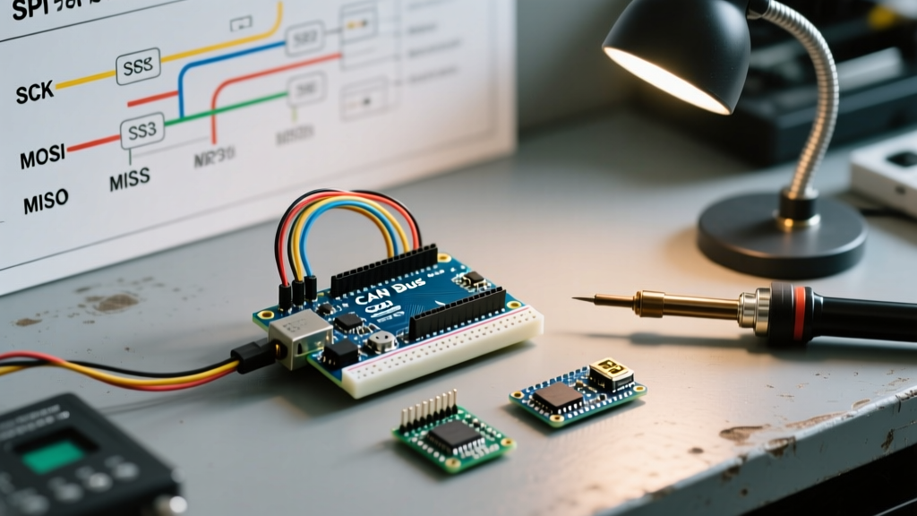
Official shields, like the Seeed Studio CAN-BUS Shield V2.0, plug directly into the standard Arduino R3 header. However, generic MCP2515 breakout modules require manual wiring. The SPI protocol demands precise pin mapping to ensure the microcontroller can configure the CAN controller's baud rate and filters.
Standard AVR SPI Pinout (Uno R3 / Nano)
- MOSI (Master Out Slave In): Pin 11
- MISO (Master In Slave Out): Pin 12
- SCK (Serial Clock): Pin 13
- CS (Chip Select): Pin 9 or 10 (Configurable in software, Pin 10 is standard for Seeed shields)
- INT (Interrupt): Pin 2 or 3 (Hardware interrupt pins on AVR)
Mega 2560 SPI Routing
A common failure point for beginners is plugging a CAN shield into a Mega 2560 and finding no communication. On the Mega, pins 11, 12, and 13 are not the primary SPI bus. The SPI bus is routed to pins 50 (MISO), 51 (MOSI), 52 (SCK), and 53 (SS). High-quality CAN bus shields route SPI through the 6-pin ICSP header, which maintains compatibility across both Uno and Mega form factors. If your generic module uses inline pins, you must manually jumper the ICSP pins to the module.
The 5V vs 3.3V Logic Level Trap
CRITICAL WARNING: Feeding 5V logic from an Arduino Uno R3 into the SPI pins of a 3.3V-rated MCP2515 module will eventually degrade or destroy the silicon. Always verify the logic level of your specific breakout board.
While the Microchip MCP2515 CAN Controller is technically rated to accept 5V VDD and 5V logic inputs on its SPI pins, many modern generic breakout boards integrate 3.3V voltage regulators and 3.3V CAN transceivers (like the SN65HVD230). If your board features an SN65HVD230, the entire module is strictly 3.3V. Connecting it directly to a 5V Arduino Uno R3 without a bidirectional logic level shifter (like the BSS138 or TXS0108E) risks frying the transceiver. Conversely, if you are using a board with an MCP2551 or TJA1050 transceiver, 5V logic is generally safe and expected.
Hardware Edge Cases: The Crystal Oscillator Mismatch
The most notorious issue in the maker community regarding CAN bus shields is the crystal oscillator mismatch. The MCP2515 relies on an external quartz crystal to calculate the time quanta for CAN bit timing. The baud rate configuration in your Arduino sketch must exactly match the physical crystal soldered onto the shield.
Identifying Your Crystal
- Inspect the silver metal oval on the MCP2515 breakout board.
- Look for the stamped frequency. It will typically read 8.000 (8 MHz) or 16.000 (16 MHz).
- Cheap modules sourced from bulk marketplaces frequently ship with 8 MHz crystals, despite product listings claiming 16 MHz.
Software Configuration Fix
When using the widely adopted mcp_can library, the initialization function requires the clock speed. If your code specifies 16 MHz but the hardware is 8 MHz, the shield will compile and initialize, but the physical bitrate will be exactly half of what you intended (e.g., trying to send at 500 kbps will actually transmit at 250 kbps), resulting in silent bus failures.
// Correct initialization for an 8MHz Crystal
CAN.begin(MCP_ANY, CAN_500KBPS, MCP_8MHz);

// Correct initialization for a 16MHz Crystal
CAN.begin(MCP_ANY, CAN_500KBPS, MCP_16MHz);
Physical Layer: Termination and Transceivers
CAN bus is a differential signaling protocol that requires proper physical termination to prevent signal reflection, which causes bit errors. According to the ISO 11898 standard, a CAN network must have exactly two 120-ohm termination resistors—one at each end of the bus.
Managing Termination on Shields
- Official Shields (Seeed V2.0): Usually feature a jumper pad or a dip switch to enable/disable the onboard 120-ohm resistor. Keep it enabled if your Arduino is at the physical end of the CAN bus; disable it if the Arduino is a middle node.
- Generic Modules: Often come with a fixed 120-ohm SMD resistor pre-soldered between CANH and CANL. If you are connecting more than two nodes on a bench test, having three or more 120-ohm resistors in parallel drops the total bus resistance below 60 ohms, which can overwhelm the transceiver's drive capability and cause the bus to crash under load. You may need to desolder the resistor on intermediate nodes.
Software Setup and Arduino SPI Reference
To ensure robust communication, always initialize the SPI bus explicitly before starting the CAN controller. The Arduino SPI Reference dictates that the Chip Select (CS) pin must be set as an OUTPUT and driven HIGH before calling SPI.begin() to prevent the MCP2515 from misinterpreting bus noise during boot.
Best Practice Initialization Sequence
#include <mcp_can.h>
#include <SPI.h>

#define CAN_CS_PIN 10
MCP_CAN CAN0(CAN_CS_PIN);

void setup() {
  Serial.begin(115200);
  pinMode(CAN_CS_PIN, OUTPUT);
  digitalWrite(CAN_CS_PIN, HIGH); // Deselect CAN controller
  SPI.begin();

  if (CAN0.begin(MCP_ANY, CAN_500KBPS, MCP_8MHz) == CAN_OK) {
    Serial.println("MCP2515 Initialized Successfully");
    CAN0.setMode(MCP_NORMAL); // Set operation mode to normal
  } else {
    Serial.println("Error Initializing MCP2515...");
    while(1); // Halt execution on hardware failure
  }
}
Summary: Shield vs. Native CAN
If you are building a project on an Arduino Uno R3 or Mega 2560, an MCP2515-based CAN bus shield is mandatory and highly effective, provided you manage the SPI routing and logic levels correctly. However, if you are starting a new design in 2026, consider migrating to an Arduino Uno R4 Minima or an ESP32-based board. These microcontrollers feature native CAN peripherals, allowing you to bypass the SPI bottleneck entirely, reduce latency, and connect directly to a $2 SN65HVD230 transceiver module without the overhead of an SPI shield library.