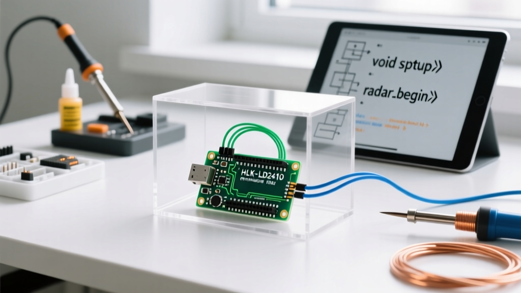

The End of the PIR Era in Precision Maker Projects
For over a decade, the HC-SR501 PIR (Passive Infrared) sensor has been the default motion detector for Arduino projects. It is cheap, ubiquitous, and requires only a single digital pin to read. However, as maker projects in 2026 demand higher reliability for smart home automation, security, and occupancy tracking, the fundamental flaws of PIR technology have become impossible to ignore. PIR sensors do not detect motion; they detect changes in thermal radiation. This leads to catastrophic failure modes in modern environments: false triggers from HVAC vents, sunlight shifting across a room, or even pets, while simultaneously failing to detect a human sitting perfectly still at a desk.
The definitive upgrade path is migrating to 24GHz FMCW (Frequency Modulated Continuous Wave) mmWave radar, specifically the Hi-Link HLK-LD2410. This guide provides a comprehensive, expert-level migration framework to replace your legacy PIR sensors with mmWave radar, covering hardware pitfalls, UART baud-rate bottlenecks, and spatial gating configurations.
Deconstructing Legacy PIR Failure Modes
Before ripping out your HC-SR501, it is crucial to understand why it fails. The HC-SR501 relies on the BISS0001 analog processing chip paired with a polyethylene Fresnel lens.
- Thermal Blindness: If the ambient room temperature approaches human skin temperature (around 93°F / 34°C), the thermal differential drops to zero, rendering the sensor completely blind.
- The Hardware Delay Trap: The BISS0001 chip enforces a mandatory hardware lockout time (adjustable via a potentiometer, but typically 3 to 5 seconds) after a trigger. During this window, the sensor is entirely deaf to new motion, making it useless for continuous presence tracking.
- Fresnel Lens Degradation: Over time, UV exposure and dust accumulation on the faceted lens scatter infrared wavelengths, shrinking the effective detection cone from 120 degrees to less than 40 degrees.
Sensor Comparison Matrix: PIR vs. Microwave vs. mmWave
When planning your migration, you will likely encounter three distinct sensor classes. Here is how they compare for a standard 5V/3.3V microcontroller ecosystem.
| Feature | HC-SR501 (PIR) | RCWL-0516 (Doppler) | HLK-LD2410 (mmWave) |
|---|---|---|---|
| Detection Method | Passive Infrared (Thermal) | Continuous Wave Doppler | FMCW Radar (24GHz) |
| Static Presence | No | No | Yes (Breathing/Micro-movement) |
| Wall Penetration | No | Yes (Major false trigger source) | No (Contained to room) |
| Interface | Digital High/Low | Digital High/Low | UART / I2C / Bluetooth |
| Typical Cost (2026) | $1.50 | $2.00 | $3.50 - $5.00 |
| Spatial Gating | No | No | Yes (Up to 8 distance gates) |
As noted by Texas Instruments in their mmWave radar overview, FMCW radar calculates both the velocity and the precise distance of a target by measuring the frequency shift between the transmitted and received chirp signals. This allows the LD2410 to tell you exactly how far away a target is, a feat impossible for PIR.
Hardware Migration: Wiring and Logic Level Pitfalls
The most common mistake makers make when upgrading to the HLK-LD2410 is frying the module's UART transceiver. The HC-SR501 outputs a 3.3V to 5V digital signal that is perfectly safe for a 5V Arduino Uno (ATmega328P). The LD2410, however, is strictly a 3.3V logic device.
CRITICAL WARNING: Connecting a 5V Arduino TX pin directly to the 3.3V RX pin of the HLK-LD2410 will cause immediate or degraded failure of the radar module's UART receiver. You must implement logic level shifting.
Safe Migration Wiring Schemes
If you are migrating an existing 5V Arduino Uno R3 project, you have two options to safely bridge the logic levels, as detailed in SparkFun's guide on logic levels:
- The BSS138 Bidirectional Logic Level Converter ($1.20): This is the professional choice. Connect the HV side to the Arduino 5V, the LV side to a 3.3V regulator, and route your TX/RX lines through the channels. It safely handles the high-speed UART transitions without signal degradation.
- The Voltage Divider (Resistors): If you are in a pinch, use a 1kΩ resistor in series with the Arduino TX line, and a 2kΩ resistor pulling the LD2410 RX line to ground. This drops the 5V signal down to a safe ~3.3V. Note: The LD2410 TX line outputting 3.3V to the Arduino 5V RX pin is safe and requires no stepping up, as the ATmega328P recognizes anything above 3.0V as a logic HIGH.
Software Migration: The 256000 Baud Rate Bottleneck
Swapping the physical sensor is only half the battle. The HC-SR501 required a simple digitalRead(). The LD2410 streams continuous hexadecimal data frames over UART.
Out of the box, the HLK-LD2410 operates at a default baud rate of 256,000 bps. This presents a massive computational hurdle for legacy 16MHz AVR microcontrollers. The standard Arduino SoftwareSerial library relies on CPU interrupts to bit-bang the serial protocol. At 256k baud, the interrupt overhead completely starves the main loop, resulting in dropped bytes, corrupted frames, and system lockups.
The Migration Solutions
To successfully migrate your codebase, you must choose one of the following architectural paths:
- Path A (Hardware Upgrade): Migrate your project from an Arduino Uno to a board with native hardware UART support, such as the Arduino Uno R4 WiFi or the Nano ESP32. These 32-bit ARM/RISC-V chips handle 256k baud on hardware serial pins effortlessly while running your main application logic.
- Path B (Firmware Downgrade): If you must stay on an 8-bit AVR, you must connect the LD2410 to a PC via a USB-to-Serial adapter (like an FT232RL) and use the manufacturer's HLK Radar Tool to permanently reconfigure the sensor's baud rate down to 9600 bps. This drastically reduces the data resolution but allows
SoftwareSerialto function without crashing the MCU.
Parsing the UART Data Frame
When using a capable board like the Nano ESP32, you will read the serial stream using the Arduino Hardware Serial reference. The LD2410 outputs a specific engineering mode frame. A standard target report frame looks like this:
F4 F3 F2 F1 [Length] AA FF 03 00 [Target State] [Move Distance] [Move Energy] [Static Distance] [Static Energy] [Gate Data...] 55 CC
Your C++ migration code must implement a ring buffer to catch the 0xF4 0xF3 0xF2 0xF1 header, read the subsequent data length byte, and parse the target state.
- 0x00: No target detected.
- 0x01: Moving target only.
- 0x02: Static target only (e.g., human reading a book).
- 0x03: Both moving and static targets present.
By extracting the Move Distance and Static Distance bytes (measured in centimeters, up to 600cm), your Arduino can now trigger automation not just based on presence, but based on proximity zones.
Advanced Configuration: Spatial Gating for False-Positive Elimination
The true power of upgrading your motion detector for Arduino lies in Spatial Gating. In a standard room, a ceiling fan or an oscillating desk fan will trigger a Doppler microwave sensor continuously. The LD2410 allows you to divide its 6-meter detection range into eight distinct 'gates' (Gate 0 to Gate 7, each representing 0.75 meters).
Using the LD2410 Arduino library, you can programmatically disable sensitivity in specific gates. For example, if your sensor is mounted on a wall and a ceiling fan occupies the space between 4.5m and 5.25m (Gates 6 and 7), you can set the motion sensitivity for those specific gates to zero, while keeping Gates 0 through 5 at maximum sensitivity. This level of environmental tuning is what separates a hobbyist prototype from a commercial-grade 2026 smart home product.
Summary of the Upgrade Path
Migrating from a legacy HC-SR501 PIR to an HLK-LD2410 mmWave radar module requires a shift in how you think about sensor integration. You are moving from a simple binary switch to a continuous spatial mapping device. By addressing the 3.3V logic level requirements, bypassing the 256k baud rate bottleneck via hardware UART, and implementing spatial gating to ignore environmental noise, your Arduino projects will achieve a level of occupancy reliability that PIR sensors simply cannot physically provide.