
Mastering the Arduino to OBD2 Connection: A 2026 Community Roundup
Connecting an Arduino to OBD2 ports remains one of the most rewarding projects in the automotive maker space. Whether you are building a custom digital dashboard, logging telemetry data to an SD card, or creating an automated shift-light system, tapping into your vehicle's Controller Area Network (CAN) or legacy K-line buses unlocks a treasure trove of real-time data. However, the ecosystem is fraught with counterfeit hardware, deprecated libraries, and electrical pitfalls that can fry your microcontroller.
In this community resource roundup, we synthesize the hard-won knowledge from automotive hacking forums, GitHub repositories, and electrical engineering wikis to give you a definitive, no-nonsense guide to establishing a reliable Arduino to OBD2 interface in 2026.
The Great ELM327 Clone Debate: What You Actually Buy
The ELM327 is the undisputed bridge chip for OBD2-to-serial translation. However, the original manufacturer, ELM Electronics, ceased operations in 2020. Consequently, the market is entirely saturated with Chinese clones. The community has developed a naming convention that is highly counterintuitive but crucial to understand:
- "Version 1.5" Clones: Counterintuitively, these are the good clones. They typically utilize a cracked firmware on a genuine PIC18F25K80 microcontroller. They support all mandatory OBD2 protocols (ISO 15765-4 CAN, ISO 14230-4 KWP, ISO 9141-2, etc.) and correctly handle the AT commands required by modern libraries.
- "Version 2.1" Clones: These are the bad clones. Manufacturers upgraded the version number for marketing, but swapped the PIC chip for a cheap STC11F04 or similar 8051-core MCU. These chips lack the memory and processing speed to handle complex CAN multiplexing, frequently dropping connections or failing to initialize on modern vehicles.
Community Hardware Comparison Matrix
| Hardware Interface | Chipset / Module | Avg. Price (2026) | Latency | Best Use Case |
|---|---|---|---|---|
| UART ELM327 (Wired) | PIC18F25K80 (v1.5 Clone) | $12 - $18 | ~20ms | Permanent dash installs, high reliability |
| Bluetooth ELM327 | HC-05 / HC-06 + ELM | $8 - $15 | ~45-80ms | Wireless logging, temporary diagnostics |
| CAN-BUS Shield | MCP2515 + TJA1050 | $18 - $25 | ~2-5ms | Direct CAN injection, high-speed telemetry |
Top Community-Backed Arduino OBD2 Libraries
Skip the outdated OBD.h libraries from 2014. The community has standardized around two highly maintained repositories that handle the messy reality of vehicle bus timing and PID parsing.
1. ELMduino (by PowerBroker2)
The ELMduino GitHub repository is the gold standard for ELM327 communication. It abstracts the AT command handshake and provides non-blocking PID queries. A standout feature is its robust handling of Bluetooth serial buffers, which historically caused memory leaks on AVR-based Arduinos.
// Example: Non-blocking RPM query using ELMduino
myELM327.sendCommand("AT Z"); // Reset
myELM327.sendCommand("AT E0"); // Echo off
myELM327.queryPID(1, 12); // Mode 01, PID 0C (Engine RPM)
2. macchina-m2 / SavvyCAN Ecosystem
For makers bypassing the ELM327 entirely and using direct CAN-BUS shields, the Macchina M2 project and SavvyCAN community provide exhaustive DBC (Database Container) files. These files map raw CAN hex IDs (like 0x0CFFF048) to human-readable signals, saving you hundreds of hours of reverse-engineering your specific car's proprietary manufacturer PIDs.
Wiring the J1962 Connector: Power Pitfalls and Pinouts
The most common point of failure in Arduino to OBD2 projects isn't software; it's electrical. The standard OBD2 J1962 female connector provides access to the vehicle's power and data buses, but it is fraught with hazards for the uninitiated.
CRITICAL WARNING: Never power a 5V Arduino directly from Pin 16.
Pin 16 supplies raw battery voltage, which sits at 12.6V with the engine off and spikes to 14.4V+ when the alternator is charging. Feeding 14.4V into the RAW pin of an Arduino Pro Micro or the barrel jack of an Uno will cause the onboard AMS1117-5.0 linear regulator to overheat and trigger thermal shutdown (or permanently fail).
The Correct Power Delivery Chain
- Tap Pin 16 (12V+) and Pin 4 (Chassis Ground). Use 18 AWG silicone wire for durability in high-heat engine bay or under-dash environments.
- Step-Down Conversion: Wire the 12V source into an LM2596 Buck Converter module (costing roughly $2.50). Adjust the potentiometer to output a stable 5.0V.
- Ignition Sensing: To prevent battery drain when the car is parked, use an optocoupler (like the PC817) to sense voltage on the ignition-switched accessory wire, signaling the Arduino to enter deep sleep via the
LowPower.hlibrary.
Standard OBD2 Pinout Reference
- Pin 4: Chassis Ground
- Pin 5: Signal Ground (Crucial for clean CAN readings)
- Pin 6: CAN High (J-2284)
- Pin 14: CAN Low (J-2284)
- Pin 16: Battery Positive (Unswitched 12V)
Bypassing ELM327: The Direct CAN-BUS Shield Approach
While the ELM327 is excellent for standardized emissions PIDs (Mode 01), it acts as a bottleneck for proprietary data like steering angle, individual tire pressures, or transmission fluid temperature. For this, the community heavily relies on the Seeed Studio CAN-BUS Shield V2.0 or generic MCP2515 modules.
The 5V vs 3.3V Logic Level Trap
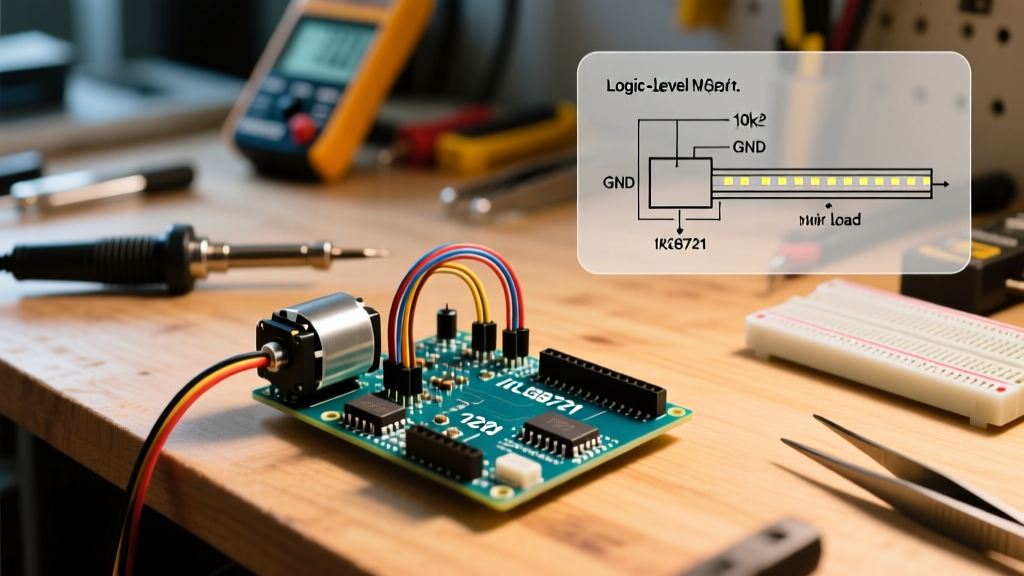
Most generic MCP2515 CAN modules purchased online utilize the TJA1050 or SN65HVD230 CAN transceiver. Here is the edge case that ruins countless projects: The MCP2515 SPI controller operates at 5V on an Arduino Uno, but modern TJA1050 transceivers often expect 3.3V logic on the TX/RX lines. Feeding 5V logic into a 3.3V transceiver can result in corrupted CAN frames or silent transceiver death. The Fix: Always use a bi-directional logic level shifter (like the BSS138 MOSFET-based module, ~$1.50) between the Arduino SPI pins and the CAN transceiver.
Troubleshooting Common Connection Failures
When your serial monitor spits out UNABLE TO CONNECT or SEARCHING... indefinitely, run through this community-vetted checklist:
1. The Ignition State Requirement
OBD2 ports are not always "live." In most vehicles post-2008, the CAN gateway module puts the OBD2 port to sleep 10 minutes after the ignition is turned off to prevent parasitic battery drain. Ensure the key is in the "ON" (Run) position, not just "ACC", when initializing the ELM327 handshake.
2. Baud Rate Mismatches on Older Vehicles
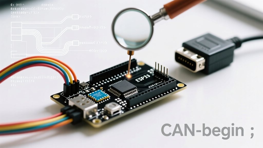
While ISO 15765-4 CAN defaults to 500 kbps, many early 2000s vehicles (especially Ford MS-CAN and older GM GMLAN) operate at 125 kbps or 33.3 kbps. If using a direct MCP2515 shield, you must manually initialize the correct baud rate in your setup function:
CAN.begin(CAN_125KBPS); // For Ford MS-CAN / Mid-speed networks3. Missing Terminating Resistors
A standard CAN-BUS requires a 120-ohm terminating resistor at both physical ends of the bus. The OBD2 port is a stub, not an end-of-line termination. If you are injecting data onto the bus via a raw CAN shield, ensure your shield has the 120-ohm jumper enabled, or the differential signal voltage will reflect and cause bus collisions, resulting in CAN_ERROR states.
Final Thoughts for the 2026 Maker
The landscape of automotive hacking has matured significantly. By avoiding "v2.1" ELM327 clones, implementing proper 12V-to-5V buck conversion, and leveraging modern non-blocking libraries like ELMduino, your Arduino to OBD2 project will transition from a fragile prototype to a reliable, road-ready telemetry system. Always consult your vehicle's specific service manual for proprietary pinouts before tapping into non-standard data buses.