
Introduction to Far-Infrared Thermography on MCUs
Integrating an Arduino thermal camera into a maker project bridges the gap between abstract data and visual environmental awareness. Whether you are building a non-contact fever scanner, a PCB hot-spot detector, or a wildlife tracking rover, far-infrared (FIR) sensor arrays provide pixelated heatmaps that standard RGB cameras cannot capture. However, configuring these sensors is rarely plug-and-play. The high data throughput required for thermal frames frequently bottlenecks standard microcontrollers, leading to I2C lockups, memory overflows, and severe frame-rate degradation.
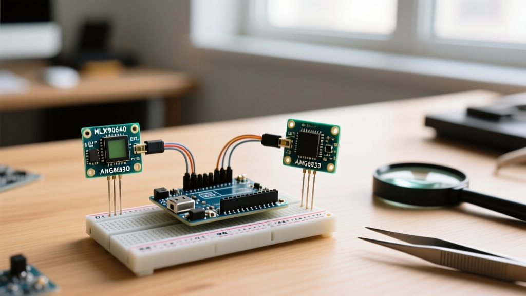
In this configuration guide, we will dissect the two dominant FIR sensors on the market—the Melexis MLX90640 and the Panasonic AMG8833 (Grid-EYE)—and detail the exact hardware, wiring, and I2C bus configurations required to get them running flawlessly on modern microcontrollers in 2026.
Hardware Showdown: MLX90640 vs. AMG8833
Before writing a single line of code, you must select the right sensor for your application. The MLX90640 and AMG8833 operate on completely different architectural paradigms.
| Feature | Melexis MLX90640 | Panasonic AMG8833 (Grid-EYE) |
|---|---|---|
| Resolution | 32 x 24 (768 pixels) | 8 x 8 (64 pixels) |
| Field of View (FOV) | 55° x 35° or 110° x 75° | 60° x 60° |
| Max Frame Rate | 64 Hz (Subpage dependent) | 10 Hz |
| I2C Address | 0x33 (Fixed) | 0x68 or 0x69 |
| Avg. Price (2026) | $60 - $75 USD | $40 - $45 USD |
| MCU RAM Requirement | ~3 KB (Buffer + Math) | ~256 Bytes |
Expert Insight: The AMG8833's 8x8 resolution is practically useless for facial recognition or detailed PCB inspection without heavy software-based bicubic interpolation. If your project requires identifying the shape of a heat source, the MLX90640 is the mandatory choice. For simple presence detection or basic HVAC thermal zoning, the AMG8833 suffices.
MCU Selection: Why the Arduino Uno Fails
A common pitfall for beginners is attempting to interface the MLX90640 with an ATmega328P-based Arduino Uno. The MLX90640 requires reading 834 16-bit words (1,668 bytes) per frame. When you factor in the floating-point math required to convert raw ADC data into Celsius temperatures, the Uno's 2 KB SRAM is instantly exhausted, resulting in silent reboots or corrupted heap memory.
Recommended MCUs for 2026:
- ESP32-S3: The gold standard for thermal cameras. Dual-core 240 MHz, 512 KB SRAM, and native USB for high-speed serial streaming to PC-based GUIs.
- Teensy 4.1: Overkill for basic I2C, but its 600 MHz Cortex-M7 and massive RAM allow for real-time on-chip bilinear interpolation and edge-detection algorithms.
- Arduino Nano 33 BLE Sense Rev2: A good compromise for low-power, battery-operated thermal logging, though its nRF52840 requires careful I2C buffer management.
Wiring & I2C Bus Configuration
Thermal cameras are notoriously sensitive to I2C bus capacitance and logic level mismatches. The Arduino Wire library defaults to 100 kHz, which is catastrophically slow for the MLX90640. At 100 kHz, reading a single frame takes over 130ms, capping your framerate at roughly 7 FPS and causing severe motion tearing.
The 3.3V vs 5V Logic Trap
Both the MLX90640 and AMG8833 are strictly 3.3V logic devices. Connecting their SDA/SCL lines directly to a 5V Arduino Mega or Uno will degrade the sensor's internal LDO and eventually fry the I2C transceivers. Always use a bidirectional logic level shifter (like the BSS138) if your MCU operates at 5V. If you are using an ESP32, you are natively in the 3.3V safe zone.
Configuring I2C Clock Speed
To achieve a usable framerate, you must push the I2C bus to Fast Mode (400 kHz) or Fast Mode Plus (1 MHz). Add the following configuration to your setup() block before initializing the sensor:
Wire.begin();
Wire.setClock(1000000); // Force 1MHz I2C Fast Mode Plus
// Note: Ensure your breakout board has 2.2k pull-up resistors to 3.3V.
// Standard 4.7k pull-ups will cause signal rise-time failures at 1MHz.
Step-by-Step MLX90640 Configuration on ESP32
For this configuration, we assume you are using the SparkFun MLX90640 Qwiic Breakout and the ESP32-S3. The official Melexis C++ driver is complex, so we will utilize the SparkFun/Adafruit wrapper libraries which handle the EEPROM compensation matrices.
- Install Dependencies: Use the Arduino Library Manager to install SparkFun MLX90640.
- Subpage Synchronization: The MLX90640 reads out in two alternating subpages (Chess pattern or Interleave pattern). If you do not configure the library to wait for the new data flag, you will capture half of Subpage 1 and half of Subpage 2, resulting in a 'venetian blind' visual artifact on moving objects. Ensure
MLX90640_SetChessMode()is called in setup. - Pin Task to Core 0: The ESP32 is dual-core. Offload the I2C polling and heavy floating-point thermal math to Core 0, leaving Core 1 free to handle Wi-Fi/Bluetooth transmission or TFT display rendering. This prevents the watchdog timer (WDT) from resetting the ESP32 during long I2C reads.
Configuring the AMG8833 for Moving Averages
If you are using the Adafruit AMG8833 Breakout, the raw data is inherently noisy. The sensor features a built-in Moving Average Mode, but it requires a specific I2C register sequence to enable, which many standard libraries skip.
To enable the hardware moving average and reduce thermal 'salt-and-pepper' noise, write the following hex sequence to the sensor immediately after boot:
// Write 0x00 to 0x01F (Reset)
// Write 0x50 to 0x01F (Moving Average Enable)
// Write 0x01 to 0x00 (Operating Mode: Normal)
Wire.beginTransmission(0x68);
Wire.write(0x07); // Average Register
Wire.write(0x20); // Enable Moving Average
Wire.endTransmission();
Troubleshooting Common Thermal Camera Failure Modes
Even with perfect wiring, environmental and electrical factors can disrupt thermal imaging. Use this diagnostic matrix to resolve edge cases.
| Symptom | Root Cause | Configuration Fix |
|---|---|---|
Wire.endTransmission() returns 1 or 2 |
I2C Bus lockup or missing pull-ups. | Add external 2.2kΩ pull-ups to 3.3V on SDA/SCL. Verify logic level shifter ground is shared with the MCU. |
Entire frame reads NaN or -273.15°C |
EEPROM calibration data read failure. | The MLX90640 requires reading 832 EEPROM words at boot. Increase I2C timeout limits in the library header file. |
| Static 'Hot Pixel' stuck at 150°C | Dead pixel compensation not applied. | Ensure the library's brokenPixel array is populated from the sensor's factory calibration registers during setup(). |
| Framerate drops to 1 FPS over time | Memory leak in float array allocation. | Declare your thermal frame buffer as a static float globally. Do not use malloc() inside the loop(). |
Optical vs. Digital Interpolation
A frequent question in the maker community is how to make an 8x8 AMG8833 look like a high-resolution camera. The answer lies in digital interpolation. By applying a Catmull-Rom spline or bicubic interpolation algorithm on the ESP32, you can upscale the 8x8 grid to a 64x64 pixel array before pushing it to an SPI TFT display. However, remember that interpolation does not add new thermal data; it merely smooths the gradients between existing pixels. If you need to detect a 2mm IC on a PCB from 10cm away, no amount of software interpolation will save you—you must upgrade to the MLX90640 or invest in a dedicated microbolometer module like the FLIR Lepton 3.5 (which requires SPI and VoSPI protocols, far beyond standard I2C configurations).
Final Calibration Pro-Tips
Thermal sensors measure the infrared radiation hitting their lens, which is heavily influenced by the sensor's own internal die temperature. Always allow your Arduino thermal camera to run for 120 seconds before taking critical measurements. This allows the internal LDO to reach thermal equilibrium. Furthermore, if your sensor is housed in a 3D-printed PLA or PETG enclosure, ensure the enclosure is painted matte black on the inside. Shiny plastics reflect ambient IR radiation back into the sensor's peripheral FOV, creating phantom heat halos around the edges of your thermal images.