
The Deceptively Simple Arduino Button: A 2026 Community Roundup
Every maker's journey begins with a blinking LED and a simple pushbutton. Yet, as projects scale from breadboard prototypes to permanent installations, the humble arduino button becomes a primary source of hardware failure, ghost inputs, and software bloat. In 2026, the maker community has moved past basic digitalRead() loops. Today, we are rounding up the most authoritative community guides, battle-tested hardware components, and robust software libraries to ensure your button inputs are flawless.
Whether you are dealing with contact bounce on an Omron tactile switch or designing a diode-multiplexed matrix for a custom macro pad, this resource roundup synthesizes the best knowledge from the electrical engineering and open-source communities.
Pro-Tip: The 330Ω Series Resistor Rule
Never wire a button directly from VCC to a microcontroller pin without a current-limiting resistor. If your code accidentally configures the pin as an OUTPUT and drives it LOW while the user presses the button, you create a dead short. A simple 220Ω to 330Ω series resistor limits the current to under 15mA, saving the ATmega328P I/O port from permanent silicon damage.
Community Hardware Picks: Switch Selection Matrix
Not all switches are created equal. Based on 2026 community consensus and datasheet analysis, here is how the most popular button types compare for microcontroller integration.
| Switch Type | Model Example | Actuation Force | Lifespan | Avg Cost (2026) |
|---|---|---|---|---|
| Standard Tactile | Omron B3F-1000 | 100gf | 100,000 cycles | $0.08 |
| Mechanical Key | Cherry MX1A-L1NN | 60gf | 100,000,000 cycles | $1.40 |
| Snap-Action Micro | Honeywell ZM10E10E01 | 100gf | 10,000,000 cycles | $0.85 |
| Capacitive Touch | TTP223 Breakout | N/A (Touch) | Infinite | $0.45 |
For standard PCB integration, the Omron B3F series remains the undisputed king of reliability. However, for user-facing interfaces where tactile feedback and longevity are paramount, the community heavily favors Cherry MX switches. If your project operates in dusty or high-moisture environments, consider sealing your tactile switches with a kapton tape layer or upgrading to IP67-rated C&K Components switches.
Wiring Physics: Pull-Ups, Pull-Downs, and Floating Pins
The most frequently asked question in the official Arduino button documentation forums revolves around erratic readings. This is almost always caused by a floating pin.
Internal Pull-Ups vs. External Pull-Downs
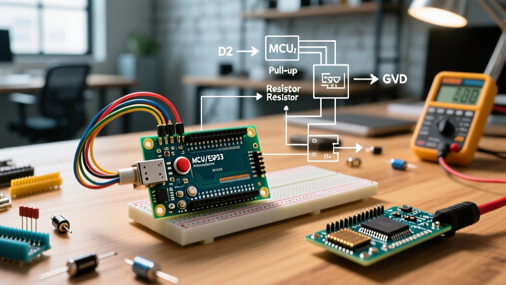
The ATmega328P microcontroller features internal pull-up resistors, typically ranging between 20kΩ and 50kΩ (nominal 32kΩ). By using pinMode(pin, INPUT_PULLUP);, you wire the button between the I/O pin and Ground. When unpressed, the pin reads HIGH; when pressed, it reads LOW.
Conversely, an external pull-down configuration requires a physical 10kΩ resistor tied to Ground, with the button switching 5V to the pin. According to the SparkFun guide on pull-up resistors, external pull-downs are preferred in environments with heavy electromagnetic interference (EMI), as the lower 10kΩ impedance makes the node less susceptible to capacitive coupling from nearby AC mains wiring.
"If your Arduino is mounted inside a metal enclosure near stepper motors or relay coils, rely on external 10kΩ pull-down resistors and shielded twisted-pair wiring for your button inputs to prevent ghost triggers."
The Best Arduino Button Libraries for 2026
Writing custom millis() based debouncing routines is a rite of passage, but it clutters your main loop. The community has standardized around three primary libraries for advanced button management.
1. Bounce2: The Industry Standard for Debouncing
Mechanical contacts physically bounce when they close, creating a rapid series of HIGH/LOW transitions lasting anywhere from 1ms to 5ms. The Bounce2 library on GitHub handles this elegantly. Unlike its predecessor, Bounce2 does not block execution with delay().
- Best feature: The
fell()androse()methods trigger exactly once per state change, perfect for toggling relays. - Pro-Configuration: Set
attach(pin, INPUT_PULLUP)andinterval(5)for modern Omron switches. Older, worn switches may require an interval of 15ms.
2. OneButton: Mastering Multi-Press Gestures
If your UI relies on double-clicks or long-presses to navigate menus, Matthias Hertel’s OneButton library is mandatory. It uses an event-driven callback architecture.
- Use Case: Single button interfaces (e.g., a smartwatch or portable sensor).
- Key Methods:
attachClick(),attachDoubleClick(), andattachLongPressStart(). - Edge Case Warning: Double-click detection inherently adds a 400ms latency to single clicks, as the library must wait to see if a second press is incoming. Do not use this for time-critical triggers like emergency stops.
3. JC_Button: Lightweight and Non-Blocking
For memory-constrained chips like the ATtiny85, JC_Button offers a minimal footprint. It strips away the complex event callbacks of OneButton in favor of a simple wasPressed() boolean check, consuming less than 200 bytes of SRAM.
Advanced Troubleshooting: Matrix Ghosting
When your project requires more than 12 buttons (like a MIDI controller or macro pad), wiring each to a dedicated I/O pin is impossible on standard boards. The solution is a button matrix (e.g., a 4x4 grid using 8 pins for 16 buttons). However, matrices introduce ghosting.
Ghosting occurs when three buttons forming a rectangle are pressed simultaneously, causing the microcontroller to falsely register the fourth corner button as pressed due to current back-feeding through the closed switches.
The Diode Solution
To eliminate ghosting, the community standard is to place a signal diode (such as the ubiquitous 1N4148 or BAT85 Schottky) in series with every single switch in the matrix. The diode's cathode (stripe) must face the row or column being driven LOW by the microcontroller. This ensures current can only flow in one direction, completely isolating the nodes and allowing full N-key rollover (NKRO).
Summary Checklist for Flawless Inputs
- Hardware: Add a 220Ω series resistor to protect the MCU pin from accidental short circuits.
- Wiring: Use
INPUT_PULLUPfor simple setups; use external 10kΩ pull-downs for high-EMI environments. - Software: Never use
delay()for debouncing. Implement Bounce2 with a 5ms interval. - Scaling: Use a diode-multiplexed matrix with 1N4148 diodes for any project exceeding 10 buttons.
By adopting these community-vetted standards, you eliminate the most common points of failure in physical computing interfaces, ensuring your hardware is as robust as your code.