
Transitioning from Breadboard to Permanent Silicon
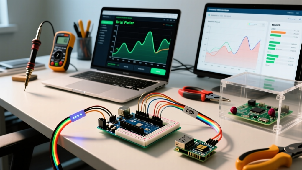
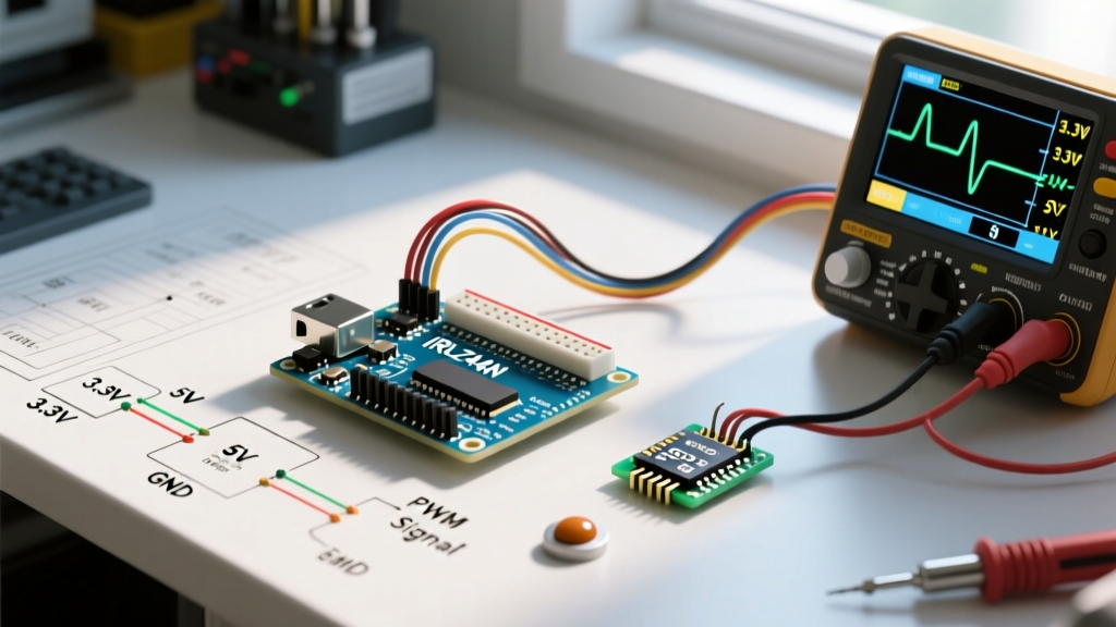
Moving a microcontroller project from a temporary solderless breadboard to a permanent, robust form factor is a critical milestone in any maker's workflow. The Arduino proto shield serves as the bridge between fragile jumper-wire prototypes and fully custom printed circuit boards (PCBs). Whether you are building a dedicated sensor node, a custom motor controller, or a standalone ATmega328P system, configuring a proto shield correctly requires deliberate layout planning and precise soldering techniques.
In this comprehensive configuration guide, we break down the anatomy of the modern proto shield, detail the optimal component placement strategies, and provide actionable soldering workflows to ensure your 2026 MCU builds are electrically sound and mechanically durable.
Anatomy of the Arduino Proto Shield Rev3
Before applying solder, you must understand the physical real estate available on the board. The official Arduino Proto Shield Rev3 (and its high-quality third-party equivalents) is built on a standard 0.1-inch (2.54mm) through-hole grid. However, it includes several specialized zones that dictate how you configure your circuit:
- Standard Prototyping Grid: The main matrix of plated through-holes, interconnected by exposed copper pads on the bottom layer. Each hole is electrically isolated unless bridged with solder or wire.
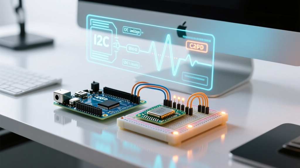
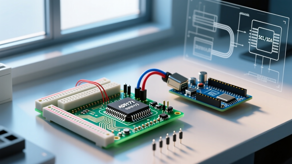
- I2C Breakout Pads: Located near the digital pins, these dedicated pads expose SDA and SCL lines, crucial for configuring modern digital sensors without consuming standard digital I/O pins.
- SOIC-16 SMD Area: A dedicated surface-mount footprint located in the center of the board, allowing you to configure and solder surface-mount ICs (like the MAX3232 or specialized op-amps) directly onto the shield.
- ISP Header Pads: A 2x3 unpopulated header footprint aligned with the standard AVR In-System Programming pinout, essential for burning bootloaders or flashing raw hex files.
- Reset Button Relocation: The Rev3 design includes pads to mount a tactile switch near the edge of the board, solving the accessibility issue of the main Arduino's reset button being covered by stacked shields.
Pre-Configuration: Planning Your Circuit Layout
The most common failure mode in shield assembly is poor spatial planning, leading to crossed wires and signal interference. Before heating your iron, map your layout. While tools like Fritzing are popular for visual representation, a physical dry-fit is mandatory.
Component Placement Matrix
Use the following matrix to determine the optimal configuration zones for different component classes on your Arduino proto shield:
| Component Class | Recommended Zone | Routing Strategy | Edge Case Warning |
|---|---|---|---|
| Microcontrollers (DIP-28) | Center Grid | Use a DIP socket; route power to inner rails | Socket wicking can block pin insertion |
| Passives (Resistors/Caps) | Adjacent to active ICs | Fly direct, bend leads flat to board | Keep decoupling caps under 5mm from IC VCC |
| Connectors (Screw/JST) | Board Perimeter | Reinforce with epoxy or heavy solder fillets | Mechanical stress can lift perimeter pads |
| SMD ICs (SOIC-16) | Dedicated SMD Pads | Use drag-soldering with Chip Quik flux | Do not mix leaded solder with RoHS SMD pads |
Step-by-Step Shield Configuration & Assembly
Step 1: Header Selection and Anti-Wicking
To connect the proto shield to your base Arduino Uno or Mega, you need female headers. Critical configuration rule: Never solder female headers directly while they are loose. Solder will wick up into the internal spring contacts via capillary action, rendering the socket useless for mating with the base board's male pins.
The Fix: Insert the female headers onto a 'dummy' male header strip or an old, sacrificial Arduino board first. Apply Kapton tape over the top of the female slots to block flux and solder splash. Solder the top-side pins to the proto shield pads. This ensures the internal contacts remain perfectly clean and properly aligned at exactly 90 degrees.
Step 2: Power and Ground Bus Routing
Do not rely on daisy-chaining component leads for power distribution; this creates voltage drops and ground loops. Instead, configure dedicated power buses using 24 AWG solid-core copper wire.
- Strip exactly 3mm of insulation from both ends of your 24 AWG wire.
- Lay the bare wire along the row of holes adjacent to the 5V and GND shield pins.
- Apply a small amount of Kester 245 no-clean flux to the wire and pads.
- Solder every third pad to secure the wire, then flow a continuous bead of solder along the entire length to create a unified, low-impedance bus.
Step 3: Signal Routing with 30 AWG Wire
For signal traces, 24 AWG is too bulky and stiff. Configure your signal paths using 30 AWG wire-wrap wire (Kynar insulated). This wire is thin enough to route tightly around DIP sockets and ICs without creating a rat's nest. Strip 2mm of Kynar insulation using a thermal wire stripper to avoid nicking the fragile copper core. Route signal wires on the top layer, and reserve the bottom layer exclusively for short, direct jumper bridges.
Standalone ATmega328P Configuration (Advanced)
One of the most powerful uses of the Arduino proto shield is configuring it as a standalone microcontroller platform, effectively turning the shield into the main brain and using the base Arduino merely as a power supply and USB-to-Serial programmer.
To configure a standalone ATmega328P-PU on the shield:
- IC Socket: Solder a low-profile DIP-28 socket in the center grid.
- Clock Source: Place a 16MHz HC49 crystal between pins 9 and 10 (XTAL1 and XTAL2).
- Load Capacitors: Configure two 22pF ceramic capacitors from each crystal leg to the ground bus.
- Decoupling: You must place a 100nF (0.1uF) ceramic capacitor across VCC (Pin 7) and GND (Pin 8), and another across AVCC (Pin 20) and GND (Pin 22). As noted in the Adafruit Perma-Proto Guide, skipping AVCC decoupling is the number one cause of erratic ADC readings in standalone builds.
- Reset Pull-up: Configure a 10kΩ resistor from Pin 1 (PC6/Reset) to the 5V bus to prevent floating resets caused by EMI.
Expert Insight: When configuring the ISP header for a standalone shield build, ensure you route the MOSI, MISO, and SCK lines to the correct ATmega pins (11, 12, and 13 respectively). Misconfiguring the ISP pinout is a frequent error that results in 'avrdude: stk500_recv(): programmer is not responding' errors when attempting to burn a bootloader.
2026 Sourcing & Cost Breakdown
The market for prototyping shields has matured, offering distinct tiers based on your project's reliability requirements. Here is the current landscape for sourcing boards:
- Genuine Arduino Proto Shield Rev3: Retailing around $16.90. Features high-quality ENIG (Electroless Nickel Immersion Gold) or HASL lead-free finish, precise 0.1" tolerances, and includes the SOIC-16 and I2C breakout pads. Best for professional portfolios and mission-critical deployments.
- Adafruit Perma-Proto (Half/Full): Priced between $9.95 and $14.50. These are not traditional 'shields' that stack directly, but rather breadboard-layout PCBs with power rails that you can mount onto* a shield base. Excellent for complex analog routing.
- Generic Clone Shields: Available on Amazon or AliExpress for $3.00 to $5.00. While cost-effective for basic LED or relay projects, 2026 teardowns show that many clones omit the I2C pull-up pads and use inferior flux that requires aggressive cleaning with isopropyl alcohol to prevent parasitic leakage currents.
Troubleshooting Common Assembly Failures
Even with meticulous planning, hardware configuration issues arise. Consult this diagnostic list before discarding a board:
- Shorted Power Rails: Use a multimeter in continuity mode. If 5V and GND beep, inspect the bottom of the board for solder bridges caused by excessive heat melting adjacent pad masks. Use MG Chemicals 416B desoldering wick to clear the bridge.
- Intermittent I2C Communication: If your OLED or BME280 sensor drops out when the shield is flexed, the I2C breakout pads likely have cold joints. Reflow with fresh 63/37 Sn/Pb eutectic solder and Amtech tacky flux.
- Reset Loop on Standalone Builds: If your custom ATmega328P configuration constantly resets, check for capacitive coupling on the reset line. Ensure your reset tactile switch is not placed parallel to high-frequency signal wires.
FAQ: Arduino Proto Shield Configuration
Can I stack multiple proto shields on top of each other?
Yes, but you must configure the inter-board connections using stacking headers (female headers with extra-long male pins extending through them). Standard female headers will not allow a second board to mate. Ensure your components on the lower shield do not exceed 8.5mm in height to avoid shorting against the copper traces of the shield above it.
How do I clean the flux residue after configuring my shield?
If you use a no-clean flux (like Kester 245), cleaning is optional but recommended for high-impedance analog circuits. Use 99% isopropyl alcohol (IPA) and a dedicated ESD-safe brush. For rosin-based fluxes, cleaning is mandatory to prevent long-term corrosion. Refer to the SparkFun Soldering Tutorial for detailed cleaning protocols and safety ventilation requirements.
What is the maximum current the proto shield traces can handle?
The standard 10mil traces on a genuine Arduino proto shield are rated for approximately 0.5A to 0.8A continuous current. If your configuration involves driving high-power servos, stepper motors, or heating elements, you must bypass the PCB traces entirely. Solder thick 18 AWG silicone wire directly from the power input headers to your motor driver terminals, using the shield only for low-current logic signals.