
The ICM-42670-P: A Modern Successor to the MPU-6050
For over a decade, the MPU-6050 dominated the maker space as the default 6-axis Inertial Measurement Unit (IMU). However, as of 2026, the ICM-42670-P from TDK InvenSense has firmly taken its place in advanced robotics, drones, and wearable tech. The ICM-42670-P offers drastically superior performance metrics: an accelerometer noise density of just 70 µg/√Hz (compared to the MPU-6050's 400 µg/√Hz) and a gyroscope noise density of 0.0028 °/s/√Hz. Furthermore, it features a 2KB FIFO buffer and ultra-low power modes essential for battery-operated IoT nodes.
Despite its advantages, integrating the ICM-42670-P with Arduino ecosystems introduces specific hardware and software compatibility hurdles. Unlike older 5V-tolerant sensors, the ICM-42670-P operates strictly between 1.71V and 3.6V on both VDD and VDDIO. This compatibility guide breaks down exact microcontroller pairings, logic level translation requirements, I2C pull-up mathematics, and SPI edge cases to ensure your ICM-42670-P Arduino projects initialize flawlessly on the first upload.
Microcontroller Compatibility Matrix
Not all Arduino-compatible boards handle 3.3V I2C/SPI protocols equally. Below is a compatibility matrix detailing how the ICM-42670-P interfaces with popular 2026 maker boards.
| Microcontroller Board | Native Logic Level | I2C Compatibility | SPI Compatibility | Required Level Shifter? |
|---|---|---|---|---|
| Arduino Uno R4 Minima | 5.0V | Native 5V pull-ups | Native 5V | Yes (BSS138 MOSFET) |
| Arduino Nano 33 IoT | 3.3V | Direct Connect | Direct Connect | No |
| ESP32-S3 DevKitC-1 | 3.3V | Direct Connect | Direct Connect | No |
| Teensy 4.1 | 3.3V | Direct Connect | Direct Connect | No |
| Arduino Uno R3 (Legacy) | 5.0V | Requires 3.3V pull-ups | Requires shifting | Yes (BSS138 MOSFET) |
Hardware Wiring & Logic Level Translation
The most common point of failure when wiring the ICM-42670-P to an Arduino is ignoring the absolute maximum ratings on the datasheet. The VDD and logic pins (SDA, SCL, SDO, CS, INT) will tolerate up to 3.6V. Feeding a 5V signal from a classic Arduino Uno directly into the SDA/SCL lines will eventually degrade the silicon's internal protection diodes, leading to erratic I2C bus lockups and permanent sensor failure.
The 5V vs 3.3V I2C Dilemma: Choosing the Right Shifter
If you are using a 5V Arduino board, you must use a bi-directional logic level shifter. However, not all shifters are created equal. Many makers mistakenly reach for the TXS0108E or TXB0104 level translators. Do not use the TXS0108E for I2C. The TXS0108E is designed for push-pull signals and features internal edge-rate accelerators and weak pull-ups that actively interfere with the open-drain nature of the I2C protocol, causing ACK/NACK bit corruption.
Instead, use a BSS138 N-channel MOSFET-based level shifter. The BSS138 circuit relies on external pull-up resistors on both the high-voltage (HV) and low-voltage (LV) sides, perfectly preserving the open-drain I2C architecture. Wire the HV side to your Arduino's 5V rail and the LV side to a stable 3.3V rail.
I2C Pull-Up Resistor Mathematics
The ICM-42670-P supports I2C Fast-mode (400 kHz) and Fast-mode Plus (1 MHz). The official Arduino Wire library defaults to 100 kHz, but leveraging the sensor's 2KB FIFO requires higher bus speeds to prevent buffer overruns. To achieve 400 kHz or 1 MHz, standard 10kΩ pull-up resistors are too weak to pull the bus high within the required rise-time limits.
According to the NXP AN10216 application note on I2C pull-up calculation, the minimum pull-up resistor value is dictated by the VOL (output low voltage) and IOL (output low current) specifications. The ICM-42670-P can sink a maximum of 3mA at 0.4V. For a 3.3V LV rail:
Rp(min) = (VDD - VOL) / IOL
Rp(min) = (3.3V - 0.4V) / 0.003A = 966 Ω
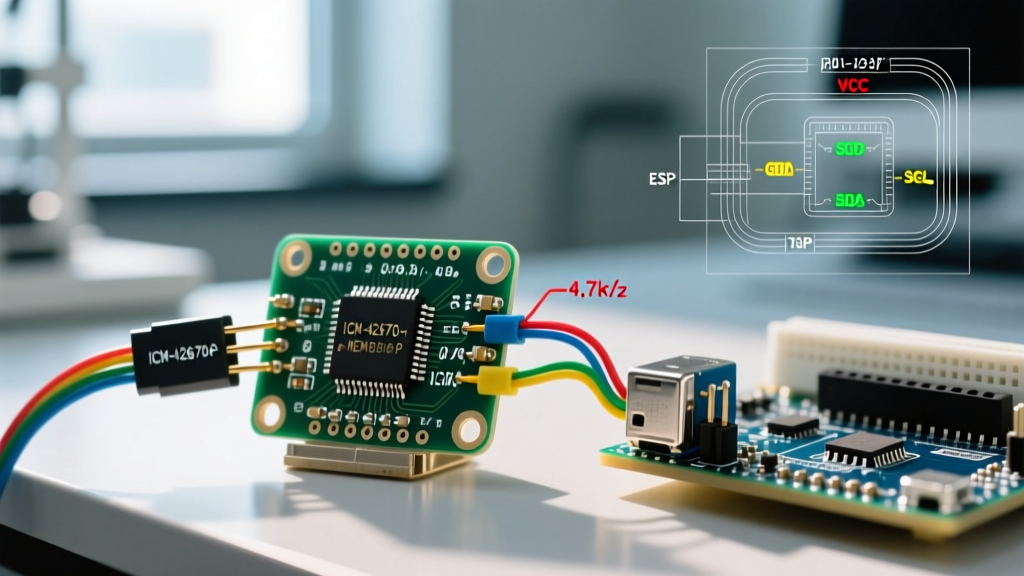
For Fast-mode Plus (1 MHz) on a breadboard with ~15pF of stray capacitance, a 1.2kΩ to 2.2kΩ pull-up resistor on the 3.3V side is optimal. Most generic ICM-42670-P breakout boards include 4.7kΩ pull-ups; for high-speed data logging, you may need to solder additional parallel resistors to lower the equivalent resistance.
SPI Mode: Speed Limits and CS Pin Quirks
If I2C bus speeds are insufficient for your high-frequency vibration analysis, the ICM-42670-P supports SPI up to 24 MHz. However, when wiring to an Arduino or ESP32 via breadboard or long jumper wires, trace inductance will cause signal ringing at 24 MHz, resulting in corrupted register reads.
Cap your SPI clock speed at 10 MHz using the Arduino SPI library:
SPI.beginTransaction(SPISettings(10000000, MSBFIRST, SPI_MODE0));Edge Case Warning: The ICM-42670-P Chip Select (CS) pin is active LOW. If you are sharing the SPI bus with other devices (like an SD card module), ensure your Arduino code explicitly drives the CS pin HIGH immediately after the transaction ends. Leaving the CS pin floating or relying solely on internal microcontroller pull-ups during boot can cause the IMU to hijack the MISO line, bricking the entire SPI bus during initialization.
Software Libraries and Address Conflicts
For Arduino IDE integration, the Adafruit ICM42670P Library remains the most robust and actively maintained option in 2026. It abstracts the complex register maps for OIS (Optical Image Stabilization) and FIFO watermark configurations.
The default I2C address is 0x68 (AD0 pin tied to GND). If you need to run two ICM-42670-P modules simultaneously on the same I2C bus—for example, to measure differential flex in a robotic arm—tie the AD0 pin of the second module to VDD (3.3V) to shift its address to 0x69. Note that AD0 must be driven to a solid logic level; leaving it floating will result in the sensor randomly toggling addresses due to EMI noise.
Advanced Troubleshooting & Edge Cases
Even with perfect wiring, makers frequently encounter initialization failures or noisy data. Here are the expert-level fixes for common ICM-42670-P edge cases:
- The FSYNC Pin Boot Failure: The ICM-42670-P features a Frame Synchronization (FSYNC) pin. If left unconnected and floating in an electrically noisy environment (e.g., near brushless motor ESCs), the sensor's internal state machine can lock up, causing
Wire.endTransmission()to return a timeout error (Code 5). Fix: Always tie the FSYNC pin directly to GND if you are not using external frame sync triggers. - Power Supply Decoupling: The internal MEMS structures are highly sensitive to voltage ripple. If your accelerometer Z-axis shows a 50/60Hz hum, your 3.3V LDO is likely inadequate. Place a 100nF (0.1µF) MLCC ceramic capacitor and a 10µF tantalum capacitor as close to the VDD and GND pins on the breakout board as physically possible.
- FIFO Watermark Interrupts: Polling the sensor via I2C in the main
loop()wastes CPU cycles and risks dropping samples. Configure the INT1 pin to trigger when the FIFO reaches a 512-byte watermark. Wire INT1 to an Arduino hardware interrupt pin (e.g., Pin 2 on an Uno, or any GPIO on an ESP32) and use a hardware ISR to read the FIFO buffer in bulk. - Gyroscope Drift on Internal Clock: The sensor defaults to an internal RC oscillator. While convenient, it suffers from temperature-induced drift. For applications requiring precise dead-reckoning, enable the internal PLL or provide an external 32.768 kHz watch crystal to the CLKIN pins to stabilize the sampling rate.
Frequently Asked Questions
Can I power the ICM-42670-P directly from an Arduino's 3.3V output pin?
Yes, but with caveats. Classic Arduino boards (like the Uno R3) use an on-board linear regulator that can only supply ~50mA to 150mA on the 3.3V rail. While the ICM-42670-P draws less than 3mA in active mode, if your breakout board includes an underpowered onboard LDO or if you are simultaneously powering an SD card, you may experience brownouts. Modern boards like the ESP32-S3 or Arduino Nano 33 IoT have dedicated, high-current 3.3V regulators that can easily handle the IMU and ancillary components.
Why does my I2C scanner find the sensor, but the Adafruit library fails to initialize?
This usually indicates an I2C bus speed mismatch or a missing pull-up on the SCL line. The Wire.begin() function initializes the bus at 100kHz. However, some breakout boards route the I2C lines through a secondary onboard multiplexer or level shifter that requires a faster clock edge to register. Try inserting Wire.setClock(400000); immediately after Wire.begin(); to force Fast-mode, which often resolves handshake timeouts in the Adafruit initialization sequence.
Is the ICM-42670-P suitable for high-vibration drone applications?
Absolutely. The "-P" variant is specifically optimized for consumer and IoT applications, featuring a programmable low-pass filter (LPF) and notch filter capabilities designed specifically to reject high-frequency motor vibrations (typically in the 150Hz to 300Hz range for 5-inch quadcopters). Ensure you configure the GYRO_ACCEL_CONFIG0 register to set the LPF bandwidth to at least half of your drone's primary rotor frequency to prevent aliasing in your PID flight controller loops.