
The Core Concept: What Makes an Arduino Tachometer Tick?
At its core, an arduino tachometer is not a physical dial, but a digital signal processing system. It translates mechanical rotation into a series of electrical pulses, which the microcontroller then converts into a human-readable Revolutions Per Minute (RPM) value. Unlike analog tachometers that rely on back-EMF voltage or mechanical centrifugal force, a digital MCU-based tachometer relies on precise timing and edge detection.
Building a reliable tachometer requires understanding three distinct phases: transduction (converting motion to electricity), signal conditioning (cleaning the electrical noise), and computational logic (calculating the final RPM). Whether you are tracking the spindle speed of a DIY CNC router or monitoring the idle speed of a small engine, the underlying physics remain identical, but the sensor choice and firmware architecture must adapt to your specific RPM range and environmental constraints.
Sensor Selection Matrix: Hall, Optical, and Inductive
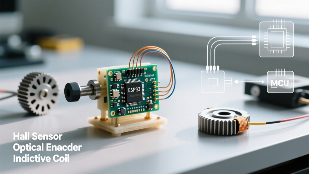
The most critical decision in your tachometer design is the transducer. Selecting the wrong sensor will lead to missed pulses at high speeds or false triggers from ambient noise. Below is a comparison of the three primary sensor types used in maker and industrial applications.
| Sensor Type | Common Model | Avg. Cost (2026) | Max Reliable RPM | Best Use Case |
|---|---|---|---|---|
| Hall Effect | A3144 / SS49E | $0.15 - $0.50 | ~15,000 RPM | Enclosed motors, dusty environments, BLDC commutation tracking. |
| Optical (Breakbeam) | TCRT5000 / HY301-21 | $1.00 - $2.50 | ~30,000 RPM | Clean environments, high-precision encoders, 3D printer extruders. |
| Inductive Proximity | LJ12A3-4-Z/BX | $8.00 - $12.00 | ~5,000 RPM | Heavy machinery, exposed metal gears, high-vibration environments. |
For most general-purpose Arduino projects, the A3144 Hall Effect sensor is the default choice. It is inexpensive, immune to dust and oil, and easily triggered by a small neodymium magnet glued to a rotating shaft. However, if you are building a high-speed optical encoder, you will want to explore Adafruit's guide on IR breakbeam sensors to understand the alignment tolerances required for optical transducers.
The Mathematics of RPM: Frequency vs. Period Measurement
A common beginner mistake is using a single mathematical approach for all speed ranges. To build a professional-grade arduino tachometer, you must understand the difference between Frequency Measurement and Period Measurement.
The Period Method (Best for Low to Medium RPM)
The period method measures the exact time elapsed between two consecutive rising edges of a pulse. Because it relies on the microcontroller's microsecond timer, it offers massive resolution at low speeds.
Formula: RPM = 60,000,000 / (Pulse_Width_µs × Pulses_Per_Revolution)
Edge Case Warning: If you are measuring a 14-pole Brushless DC (BLDC) motor using its back-EMF or Hall sensors, the sensor will output 7 electrical pulses per single mechanical revolution. If you fail to divide by the pole-pair count in your firmware, your calculated RPM will be 700% higher than the actual physical shaft speed.
The Frequency Method (Best for High RPM)
At extremely high speeds (e.g., >10,000 RPM), the time between pulses becomes so short that microsecond timer overflow and interrupt latency can introduce jitter. The frequency method solves this by counting the total number of pulses that occur within a fixed time window (usually exactly 1.0 seconds).
Formula: RPM = (Total_Pulses_in_1_Second × 60) / Pulses_Per_Revolution
While highly accurate at high speeds, the frequency method suffers from severe quantization error at low speeds. If a motor is spinning at 30 RPM (0.5 Hz), a 1-second sampling window might count 0 pulses or 1 pulse, resulting in a calculated RPM of either 0 or 60. Advanced tachometers use a hybrid algorithm that switches between period and frequency methods based on a dynamic threshold.
Hardware Interfacing and Signal Conditioning
Raw sensor signals are rarely clean enough to be fed directly into an Arduino's digital input pins, especially in motor-control environments. Motors generate massive amounts of Electromagnetic Interference (EMI) and voltage spikes.
- Pull-Up Resistors: Most Hall effect sensors (like the A3144) feature an open-collector output. This means they can pull the signal line to ground, but cannot drive it high. You must use a 10kΩ pull-up resistor connected between the sensor's output pin and the Arduino's 5V (or 3.3V) rail.
- Schmitt Triggers: If your signal cable runs longer than 12 inches, it will act as an antenna, picking up high-frequency noise. Passing the signal through a 74HC14 Hex Inverting Schmitt Trigger ($0.30) cleans up slow-rising edges and rejects sub-threshold noise spikes, ensuring the Arduino only sees crisp, square digital pulses.
- Decoupling: Always place a 0.1µF ceramic capacitor as close to the sensor's VCC and GND pins as physically possible. For the Arduino itself, ensure a 100µF bulk electrolytic capacitor is on the 5V rail to prevent brownouts when the motor draws sudden current.
Firmware Architecture: Mastering Interrupts
Polling a sensor pin inside the loop() function using digitalRead() is a guaranteed way to miss pulses, especially if your code is also updating an LCD display or handling serial communications. A robust arduino tachometer relies on hardware interrupts.
By utilizing the Arduino attachInterrupt() documentation, you can configure the MCU to instantly pause the main program, record the exact microsecond timestamp of the pulse, and resume.
When writing your Interrupt Service Routine (ISR), adhere to these strict rules:
- Keep the ISR as short as possible. Do not use
Serial.print()ordelay()inside the ISR. - Declare any variables shared between the ISR and the main loop as
volatile. - When reading a multi-byte
volatilevariable (like anunsigned longtimestamp) in the main loop, temporarily disable interrupts usingnoInterrupts(), copy the value to a local variable, and re-enable them withinterrupts(). This prevents data tearing, where the ISR updates the variable halfway through your read operation.
Real-World Failure Modes and EMI Mitigation
Even with perfect code, physical environments will test your tachometer. Here are the most common failure modes encountered in the field and how to solve them.
1. Contact Bounce and Phantom Pulses
If you are using a mechanical reed switch instead of a solid-state Hall sensor, the physical metal contacts will bounce upon closure, generating dozens of micro-pulses in a single millisecond. The Arduino will interpret this as the motor spinning at 500,000 RPM. You must implement software debouncing. Refer to the Arduino Debounce example to implement a state-machine that ignores subsequent edges for a 5-millisecond window after the first trigger.
2. Ground Loops and Common-Mode Noise
If your Arduino is powered via USB from a laptop, and the motor is powered by a separate 24V switching power supply, the ground potential between the two systems can fluctuate wildly. This causes the Arduino to read phantom HIGH signals. Solution: Use an optocoupler (like the PC817, approx. $0.10) to electrically isolate the motor's sensor ground from the Arduino's logic ground. The optocoupler transmits the pulse via light, completely breaking the electrical ground loop.
3. Missed Pulses at Extreme RPM
If your motor exceeds 20,000 RPM and you are using a standard Arduino Uno (ATmega328P running at 16MHz), the overhead of entering and exiting the ISR might take 5-10 microseconds. If the pulse width from your sensor is shorter than the ISR execution time, you will drop pulses. To fix this, you must either use a faster MCU (like the Teensy 4.1 running at 600MHz) or use hardware timer capture pins (Input Capture Unit) which log the timestamp in hardware without CPU intervention.
Frequently Asked Questions
Can I use an analog sensor for a tachometer?
Yes, sensors like the SS49E provide a linear analog voltage proportional to magnetic field strength. However, for RPM counting, digital Hall switches (A3144) are vastly superior because they output clean square waves that don't require analog-to-digital conversion or complex thresholding in software.
Why is my RPM reading fluctuating by ±50 RPM at idle?
This is usually caused by mechanical runout (the magnet is not perfectly centered on the shaft) or a loose timing belt causing micro-slippage. If the mechanical system is verified, add an Exponential Moving Average (EMA) filter in your firmware to smooth out the display output without introducing the lag associated with standard averaging.