
The Enduring Appeal of Physical Keypads in 2026
While capacitive touchscreens and gesture sensors have proliferated across consumer electronics, the physical keypad for Arduino projects remains an indispensable input method. In industrial control panels, outdoor security gates, and heavy-machinery interfaces where operators wear gloves, physical tactile feedback is not just a preference—it is a safety requirement. As of 2026, the maker community has heavily stress-tested various keypad topologies, from ultra-cheap membrane matrices to premium I2C multiplexed modules. This community resource roundup synthesizes field data, failure modes, and procurement insights to help you select the exact input hardware your microcontroller project demands.
Community Comparison Matrix: Top Keypad Architectures
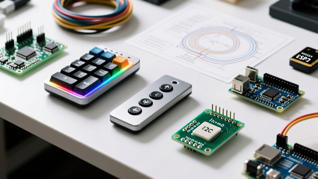
Not all keypads are created equal. The choice between a direct matrix scan and an I2C bus interface dictates your pin budget, wiring complexity, and software overhead. Below is a breakdown of the most widely deployed options in the Arduino ecosystem today.
| Keypad Type | Standard Model / Example | Interface | MCU Pins Required | Avg Price (2026) | Best Application |
|---|---|---|---|---|---|
| Membrane 4x4 Matrix | HiLetgo / Elegoo Generic | Direct GPIO Matrix | 8 Pins | $1.50 - $3.00 | Security PIN pads, basic menus |
| Mechanical 3x4 Matrix | SparkFun / Generic Cherry-style | Direct GPIO Matrix | 7 Pins | $12.00 - $18.00 | High-reliability industrial, CNC pendants |
| I2C LED Keypad | Adafruit Trellis (PID 1616) | I2C Bus | 2 Pins (SDA/SCL) | $19.95 - $24.95 | Audio sequencers, MIDI controllers |
| Capacitive Touch I2C | Seeed Grove 12-Key (SKU 111020012) | I2C Bus | 2 Pins (SDA/SCL) | $12.00 - $14.00 | Sealed enclosures, medical, wet environments |
Deep Dive: Matrix Scanning Mechanics and Pin Optimization
The standard 4x4 membrane keypad utilizes a row-column matrix. Instead of requiring 16 individual input pins, the microcontroller scans 8 pins (4 rows, 4 columns) by driving the rows LOW one at a time and reading the columns. If a column reads LOW, the intersection key is pressed.
The Pull-Up Resistor Imperative
A frequent pitfall for beginners is floating inputs on the column pins. You must enable the microcontroller's internal pull-up resistors. According to the official Arduino PinMode reference, setting your column pins to INPUT_PULLUP activates an internal 20kΩ to 50kΩ resistor, pulling the line HIGH until a row driven LOW bridges the connection. This eliminates the need for external resistor networks, saving board space and soldering time.
Community Wisdom: "Never use external 10kΩ pull-ups on long ribbon cable runs for matrix keypads. The parasitic capacitance of a 2-meter ribbon cable combined with 10kΩ resistors creates an RC delay that causes false triggers. Stick to internal INPUT_PULLUP or use 4.7kΩ external pull-ups if operating in high-EMI industrial environments." — HardwareHacker99, EEVBlog Forums
Real-World Failure Modes & Edge Cases
When integrating a keypad for Arduino in field-deployed hardware, you must anticipate physical and electrical degradation. Here are the most common failure modes documented by the community:
1. FPC Ribbon Cable Fatigue
The Flexible Printed Circuit (FPC) tail on generic $2 membrane keypads is notoriously fragile. Repeated bending at the exit point of the enclosure causes the silver-polymer traces to micro-fracture. The Fix: Apply a 1-inch strip of Kapton tape (polyimide) over the bend radius to distribute mechanical stress, and use a hot-melt glue bead at the connector housing to prevent lateral shearing.
2. Matrix Ghosting and Key Masking
Ghosting occurs when three keys forming an 'L' shape are pressed simultaneously, causing the controller to register a fourth 'phantom' key press. This happens because current flows backward through the closed switches into an adjacent column. While premium keyboards include a 1N4148 signal diode in series with every switch node to block reverse current, cheap Arduino membrane pads omit these diodes to cut costs. The Workaround: If your project requires multi-key presses (like a chorded keyboard or gaming pad), you must either design a custom PCB with diodes or switch to an I2C multiplexed keypad like the Adafruit Trellis, which handles individual switch isolation via its HT16K33 driver chip.
3. Contact Oxidation and Bounce
Membrane pads rely on carbon pills pressing against silver traces. In high-humidity environments, these traces oxidize, increasing contact resistance. This manifests as 'key bounce' or missed presses. While the standard Arduino Keypad Library defaults to a 10ms debounce delay, worn or oxidized membrane pads often require bumping this parameter to 25ms or 30ms in the library configuration to stabilize the input.
Step-by-Step: Wiring and Scanning a 4x4 Matrix
For standard applications, the direct GPIO matrix remains the most cost-effective solution. Follow this optimized wiring protocol:
- Identify Pin 1: Look for the small black arrow or '1' printed on the FPC connector. Pin 1 is typically Row 1, and Pin 8 is Column 4.
- Assign GPIOs: Connect Rows (Pins 1-4) to digital pins 9, 8, 7, 6. Connect Columns (Pins 5-8) to digital pins 5, 4, 3, 2.
- Library Initialization: Install the
Keypadlibrary by Mark Stanley via the Library Manager. - Multi-Key Handling: Do not use the basic
getKey()function if you need to hold a modifier key (like 'Shift' or '*') while pressing a number. Instead, use theMultiKeyexample sketch included in the library, which tracks an array of currently pressed keys and their states (IDLE, PRESSED, HOLD, RELEASED).
The I2C Alternative: When Pin Budget is Critical
If you are building a complex IoT device using an ESP32 or a pin-starved ATtiny85, dedicating 8 GPIOs to a keypad is unfeasible. The community heavily recommends migrating to I2C-based keypads. The Adafruit Trellis is a standout open-source design. It utilizes the HT16K33 chip to scan up to 16 keys and drive 16 LEDs using only the SDA and SCL lines. Furthermore, because the scanning happens entirely on the dedicated silicon, the microcontroller is freed from the continuous polling loop required by direct matrix scanning, allowing for deeper sleep states and better battery life in portable sensor arrays.
Procurement & Sourcing Checklist for Makers
When ordering keypads in bulk from distributors like Mouser, Digi-Key, or AliExpress for your 2026 production runs, verify the following specifications:
- FPC Pitch: Standard hobbyist keypads use a 2.54mm (0.1") pitch, which mates perfectly with standard 0.1" Dupont headers. However, some ultra-slim consumer replacements use 1.0mm or 1.25mm pitch. These will require an FPC-to-DIP adapter board to interface with an Arduino.
- Actuation Force: Membrane pads typically require 160g to 200g of force. Mechanical matrix switches range from 45g (light touch) to 80g (tactile bump). Choose based on whether the user will be pressing with a bare fingertip or a gloved hand.
- IP Rating: If deploying outdoors, ensure the membrane overlay is rated at least IP65 to prevent moisture ingress from shorting the matrix layers.
Final Verdict
For rapid prototyping, indoor DIY security systems, and budget-conscious educational kits, the generic 4x4 membrane matrix remains the undisputed champion of accessibility. However, for commercial enclosures, high-vibration environments, or projects requiring simultaneous key presses, investing in mechanical matrix boards or I2C multiplexed modules will save you weeks of software debouncing and hardware troubleshooting. Always match the physical topology to your environmental constraints, and leverage the INPUT_PULLUP and multi-key library functions to ensure robust, noise-immune operation.