
The Ecosystem of Arduino Stepper Control
Building a reliable CNC router, 3D printer, or robotic actuator requires more than just connecting wires and uploading a sketch. True arduino stepper control mastery lies in understanding the electrical and logical compatibility between your microcontroller unit (MCU), the stepper driver, and the physical motor. In 2026, the maker market is saturated with options ranging from legacy 8-bit boards to advanced 32-bit ARM and RISC-V architectures. Mismatching these components leads to missed steps, excessive acoustic noise, thermal shutdowns, and in worst-case scenarios, catastrophic silicon failure.
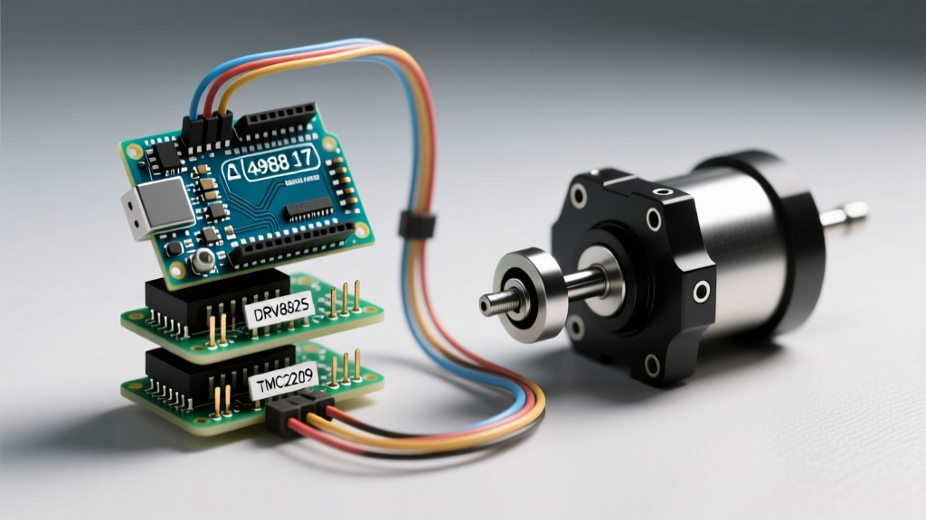
This compatibility guide dissects the exact electrical thresholds, current ratings, and logic-level requirements to ensure your next motion control project operates flawlessly. We will evaluate the most common driver ICs—namely the A4988, DRV8825, TMC2209, and TB6600—against popular NEMA 17 and NEMA 23 stepper motors.
The Logic Level Bottleneck: 5V vs 3.3V MCUs
The most frequent point of failure in modern arduino stepper control projects stems from logic level mismatches. Historically, the Arduino Uno R3 (based on the ATmega328P) operated at 5V logic. Today, makers frequently use the Arduino Nano 33 IoT, ESP32, or Raspberry Pi Pico (programmed via the Arduino IDE), which operate at 3.3V logic.
Evaluating Driver Logic Thresholds
According to the Texas Instruments DRV8825 Datasheet, the logic high input voltage (VIH) threshold is 2.2V. Theoretically, a 3.3V MCU output easily clears this threshold. However, in high-electromagnetic interference (EMI) environments—such as a chassis housing unshielded stepper motors and switching power supplies—a 3.3V signal is highly susceptible to ringing and voltage droop. This noise can cause the driver to register false STEP pulses, resulting in layer shifts in 3D printing or ruined toolpaths in CNC milling.
- A4988 & DRV8825: Technically compatible with 3.3V logic, but highly recommended to use a logic level shifter (like the CD4050 non-inverting buffer) for noise margin safety in industrial or high-EMI environments.
- TMC2209: Explicitly designed with 3.3V to 5V tolerant logic inputs. It is the undisputed champion for 3.3V MCUs like the ESP32 and Nano 33 IoT.
- TB6600 (External Driver): Uses internal optocouplers that typically require 5V to 24V to properly forward-bias the internal LED. Connecting a 3.3V MCU directly to a TB6600 PUL+ pin will often result in zero motor movement. A level shifter or a simple NPN transistor switching circuit is mandatory.
Motor-to-Driver Current and Voltage Matching Matrix
Selecting a driver based solely on physical footprint is a critical error. You must match the driver's continuous current capability and voltage tolerance to the motor's coil resistance and rated current. Below is a compatibility matrix based on current 2026 market pricing and specifications.
| Motor Model (NEMA) | Coil Resistance | Rated Current / Phase | Recommended Driver | Max Continuous Current | Est. Driver Cost |
|---|---|---|---|---|---|
| LDO-42STH47-1684AC (17) | 1.65 Ω | 1.68 A | TMC2209 / DRV8825 | 2.0 A (RMS) / 2.5 A | $12 / $5 |
| StepperOnline 17HS19-2004S1 (17) | 1.40 Ω | 2.00 A | TB6600 / DRV8825 | 4.0 A / 2.5 A | $18 / $5 |
| StepperOnline 23HS45 (23) | 1.80 Ω | 3.00 A | TB6600 / DM542T | 4.0 A / 4.2 A | $22 / $45 |
Note: The TMC2209's 2.0A RMS rating assumes adequate active cooling (heatsink and 40mm fan). Without forced air, continuous current should be derated to 1.2A RMS to prevent thermal shutdown.
Power Supply Sizing and the Inductance Bottleneck
A common misconception in arduino stepper control is that the power supply voltage should match the motor's rated voltage (Calculated as V = I × R). For the LDO-42STH47-1684AC, the rated voltage is a mere 2.77V (1.68A × 1.65Ω). Supplying 2.77V to a chopper driver will result in abysmal high-speed torque.
As detailed in the Texas Instruments Application Report on Stepper Motor Drive Voltage, the driver uses Pulse Width Modulation (PWM) to chop a higher voltage down to the motor's rated current. Higher bus voltages force current into the motor's inductive coils faster, maintaining torque at high RPMs. The industry rule of thumb is to supply a bus voltage 4 to 10 times the motor's rated voltage.
Voltage Recommendations by Form Factor
- NEMA 17 (Low Inductance < 3mH): 24V DC is the optimal sweet spot. It provides excellent high-speed torque without exceeding the 35V absolute maximum rating of most carrier-board capacitors.
- NEMA 17 (High Inductance > 4mH): 36V DC to 48V DC. Required to overcome the inductive reactance at speed, provided your driver (like the TMC2209 or TB6600) supports up to 48V.
- NEMA 23 (CNC Spindles/Router Axes): 48V DC to 68V DC. Drivers like the DM542T are specifically engineered for these higher bus voltages to move heavy gantries rapidly.
Microstepping, Decay Modes, and Acoustic Noise
Microstepping divides a full 1.8° step into smaller increments (e.g., 1/16, 1/32, 1/256), smoothing motion and reducing low-speed resonance. However, the method of microstepping dictates compatibility and noise levels.
Legacy drivers like the A4988 use a fixed mixed-decay current regulation scheme. This results in audible whining and significant resonance at specific mid-range speeds. The DRV8825 improved upon this with a longer fast-decay time, but still suffers from acoustic noise.
The Trinamic TMC2209 revolutionized arduino stepper control by introducing two distinct modes:
- StealthChop2: A voltage-based PWM regulation that renders the motor virtually silent at low to medium speeds. Ideal for 3D printer extruders and desktop CNC enclosures.
- SpreadCycle: A highly precise current-based hysteresis decay mode. It generates more acoustic noise but provides superior high-speed torque and prevents missed steps during rapid directional changes.
For advanced configuration, the Marlin Firmware TMC Driver Documentation provides an excellent framework for understanding how UART communication allows the MCU to dynamically switch between StealthChop and SpreadCycle on the fly, a feature impossible with hardware-jumpered drivers like the A4988.
Field Note: The UART Advantage
To utilize the TMC2209's advanced features (like StallGuard sensorless homing), you must wire the MS1 and MS2 pins to your MCU's hardware or software serial TX/RX lines. Do not use hardware jumpers on these pins when operating in UART mode, as they dictate the slave address (0-3) for multi-axis communication on a single serial bus.
Common Failure Modes and Wiring Edge Cases
Even with perfect component compatibility, improper wiring practices will destroy your hardware. Be vigilant against these specific failure modes:
1. The Hot-Swap Inductive Kickback
Never disconnect or reconnect a stepper motor from the driver while the power supply is active. The motor coils act as massive inductors. Breaking the circuit under load generates a back-EMF voltage spike that can easily exceed 100V, instantly punching through the driver's internal H-bridge MOSFETs and permanently shorting the IC. Always power down the 24V/48V bus before touching motor connectors.
2. Missing VMOT Decoupling Capacitors
Pololu-style carrier boards (A4988, DRV8825) include a small ceramic capacitor, but it is insufficient to handle the regenerative braking energy returned by the motor during rapid deceleration. You must solder or wire an additional 100µF to 220µF low-ESR electrolytic capacitor directly across the VMOT and GND pins on the carrier board. Failure to do so will result in voltage spikes that reset your Arduino or fry the driver.
3. Ground Loop and Logic Isolation Errors
When using external high-voltage drivers like the TB6600 alongside a 5V Arduino Uno, the grounds must be unified. The TB6600 PUL-, DIR-, and EN- pins are optocoupler cathodes. They must connect to the Arduino's GND. If you attempt to control them using only the signal pins without a common ground reference, the optocouplers will not trigger, and the motor will remain locked or unpowered.
Software Libraries: AccelStepper vs. TMCStepper
Hardware compatibility is only half the battle; your software stack must match the driver's capabilities.
- AccelStepper: The gold standard for generating STEP and DIR pulses with trapezoidal acceleration profiles. It is driver-agnostic and works perfectly with A4988, DRV8825, and TB6600 setups. However, it cannot configure driver-specific internal registers.
- TMCStepper: Mandatory if you are using Trinamic ICs (TMC2209, TMC2130, TMC5160) over UART or SPI. You will typically use both libraries in tandem: TMCStepper to initialize the RMS current, microstep resolution, and decay mode during the
setup()loop, and AccelStepper to handle the real-time motion profiling in theloop().
Summary
Achieving robust arduino stepper control requires a holistic approach to compatibility. Match 3.3V MCUs with TMC2209 drivers to avoid logic threshold issues, size your power supply to 4x-10x the motor's rated voltage to defeat coil inductance, and always implement proper decoupling and flyback protection. By respecting the electrical boundaries of your components, you transition from unreliable hobbyist prototypes to industrial-grade motion systems.