
The Hidden Cost of Poorly Configured Interrupts
When configuring interrupts on Arduino boards, makers frequently encounter silent failures: missed encoder pulses, ghost triggers from electromagnetic interference (EMI), or complete system lockups. Whether you are building a CNC limit-switch safety circuit, an anemometer pulse counter, or a high-speed tachometer, an unreliable Interrupt Service Routine (ISR) can lead to catastrophic hardware damage or corrupted data.
This guide bypasses basic theory and dives directly into advanced troubleshooting. We will diagnose architecture-specific quirks across the classic ATmega328P (Uno/Nano), the modern ATmega4809 (Nano Every), and the ESP32 family, providing exact hardware values and software patterns to stabilize your ISR execution.
Diagnostic Matrix: Symptom vs. Root Cause
Before rewriting code, map your specific failure mode to the matrix below. This diagnostic framework isolates whether your issue is electrical, architectural, or syntactical.
| Symptom | Root Cause | Targeted Solution |
|---|---|---|
| Multiple triggers per single physical press | Mechanical switch bounce (1-5ms chatter) | Hardware RC low-pass filter or software micros() debounce |
| Random triggers with no physical input | Floating pin / High-impedance EMI pickup | Enable internal pull-ups or add 10kΩ external pull-up resistors |
| Missed rapid pulses at high RPM | ISR execution time exceeds pulse interval | Strip ISR to bare minimum; defer processing to main loop |
| Variables not updating in main loop | Missing volatile keyword on shared variables |
Declare all ISR-shared variables as volatile |
| ESP32 Guru Meditation Error / Panic | ISR executing from Flash cache during Wi-Fi/BLE events | Tag ISR function with IRAM_ATTR |
| Corrupted multi-byte variable reads | Non-atomic memory access (tearing) | Use noInterrupts() when copying multi-byte variables in main loop |
Fix 1: Eradicating Ghost Triggers and Switch Bounce
Mechanical switches do not make clean electrical contact. The metal contacts physically bounce, creating a rapid series of HIGH/LOW transitions lasting anywhere from 1ms to 10ms. If your ISR is configured to trigger on CHANGE or FALLING, a single button press can register as dozens of interrupts.
Hardware Filtering (The 100nF Rule)
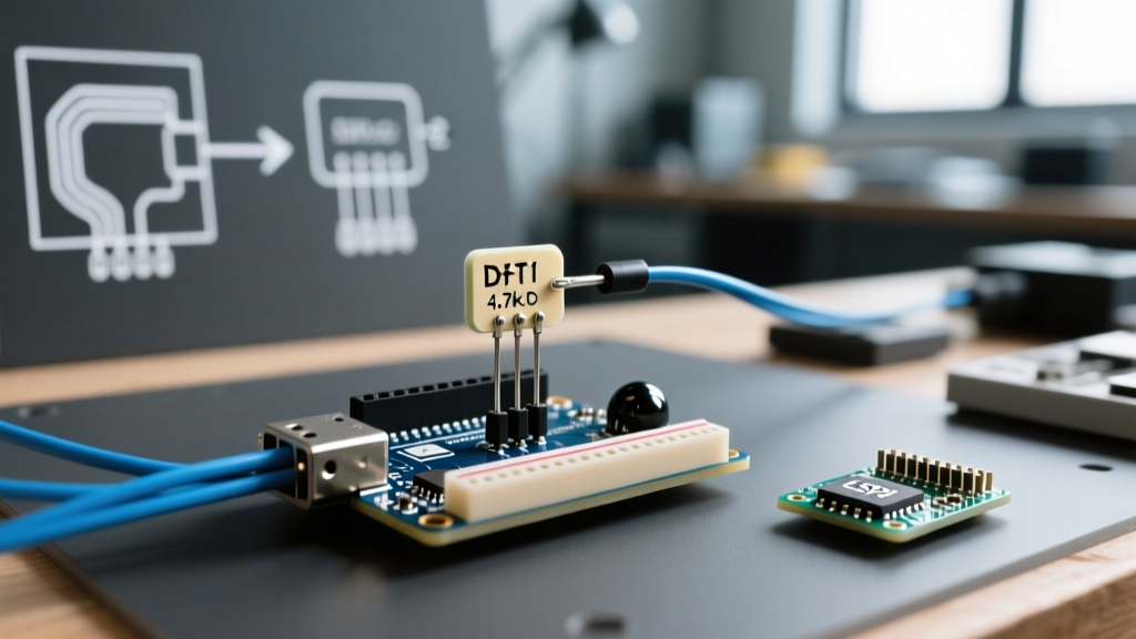
The most robust way to handle interrupts on Arduino inputs connected to mechanical switches is hardware debouncing. Do not rely solely on software. Build a simple RC (Resistor-Capacitor) low-pass filter directly at the GPIO pin.
- Resistor: 10kΩ pull-up to 5V (or 3.3V on ESP32).
- Capacitor: 100nF (0.1µF) ceramic capacitor from the GPIO pin to GND.
- Time Constant (τ): τ = R × C = 10,000 × 0.0000001 = 1ms. This smooths out the sub-millisecond bounce spikes.
Pro-Tip: For industrial environments with heavy relay switching or motor noise, follow the RC filter with a Schmitt Trigger IC (like the 74HC14) to provide sharp hysteresis and eliminate edge ringing.
Software Debouncing (Without delay())
If hardware filtering is impossible, you must debounce in software. Never use delay() inside an ISR. The delay() function relies on millis(), which itself relies on timer interrupts. Calling it inside an ISR will deadlock your microcontroller instantly.
Instead, use micros() to enforce a lockout period:
volatile unsigned long lastInterruptTime = 0;

void IRAM_ATTR handleInterrupt() {
  unsigned long currentTime = micros();
  // Ignore triggers occurring within 2000 microseconds (2ms) of the last
  if (currentTime - lastInterruptTime > 2000) {
    // Valid trigger logic here
    pulseCount++;
  }
  lastInterruptTime = currentTime;
}
Fix 2: Navigating Architecture Limitations (INT vs. PCINT)
A common troubleshooting dead-end occurs when makers attempt to attach interrupts to unsupported pins. The rules change drastically depending on your silicon.
The ATmega328P (Uno / Nano) Bottleneck
The classic ATmega328P only supports true External Interrupts (INT0 and INT1) on Digital Pins 2 and 3. If you call attachInterrupt() on Pin 4, it will silently fail or map incorrectly depending on your core version.
If you need interrupts on other pins (e.g., A0-A5 or D4-D13), you must use Pin Change Interrupts (PCINT). PCINTs group pins into three port vectors (PCINT0, PCINT1, PCINT2). The hardware will tell you that a pin changed, but not which pin. You must manually read the port registers inside the ISR to determine the culprit.
The ESP32 and IRAM_ATTR Requirement
On ESP32 and ESP32-S3 boards, every GPIO supports interrupts. However, the dual-core Xtensa/LX6 architecture executes code from external SPI Flash. When Wi-Fi or Bluetooth events occur, the Flash cache is temporarily disabled. If your ISR resides in Flash, the CPU will attempt to fetch instructions from disabled memory, resulting in a fatal Guru Meditation Error and a system reboot.
Critical Fix: Always prepend your ESP32 ISR functions with the
IRAM_ATTRattribute. This forces the compiler to place the function in the internal Static RAM (IRAM), ensuring it remains accessible even when the Flash cache is suspended.
For deeper architectural insights on Espressif silicon, consult the official ESP32 Arduino Core GPIO Documentation.
Fix 3: Resolving Missed Pulses and ISR Bloat
If you are reading a high-speed optical encoder (e.g., 1024 PPR at 3000 RPM), your MCU might be missing pulses. This happens when the ISR execution time exceeds the interval between pulses.
Stripping the ISR to the Bare Minimum
An ISR should only update state and set a flag. It should never perform Serial printing, I2C transactions, or complex math. Serial communication relies on background interrupts; blocking inside your ISR will corrupt the UART buffer.
Bad ISR:
void badISR() {
  Serial.println('Triggered!'); // BLOCKS EXECUTION, CAUSES MISSED PULSES
  rpm = calculateRPM(millis()); // Complex math delays exit
}
Optimized ISR:
volatile bool pulseReceived = false;
volatile unsigned long pulseTimestamp = 0;

void optimizedISR() {
  pulseTimestamp = micros();
  pulseReceived = true;
}
Fix 4: The volatile Keyword and Atomic Operations
The most insidious bug in Arduino interrupt programming is data tearing. When you declare a variable as volatile, you tell the compiler not to cache it in CPU registers, forcing a read from SRAM every time. However, volatile does not make operations atomic.
On an 8-bit AVR (Uno/Nano), reading a 32-bit unsigned long requires four separate 8-bit memory fetches. If an interrupt fires between the second and third fetch, the main loop reads a corrupted, hybrid value.
Implementing Atomic Copies
Whenever you read a multi-byte volatile variable in your main loop(), you must temporarily disable interrupts to ensure an atomic read.
volatile unsigned long isrPulseCount = 0;
unsigned long localPulseCount = 0;

void loop() {
  // Disable interrupts for the few microseconds it takes to copy 4 bytes
  noInterrupts();
  localPulseCount = isrPulseCount;
  interrupts();   // Re-enable immediately

  // Perform heavy math and Serial printing using the local copy
  Serial.println(localPulseCount * 2.5);
}
For a comprehensive deep-dive into how the AVR compiler handles memory and interrupt vectors, Nick Gammon's authoritative guide on AVR interrupts remains the gold standard for understanding the underlying C++ mechanics.
Summary Checklist for Stable Interrupts
- Hardware: Use 10kΩ pull-ups and 100nF capacitors for all mechanical inputs.
- Syntax: Declare all shared variables as
volatile. - Execution: Keep ISRs under 5µs. No
delay(), noSerial.print(), no I2C. - Architecture: Use
IRAM_ATTRon ESP32; respect INT vs PCINT limits on ATmega328P. - Atomicity: Wrap multi-byte variable reads in the main loop with
noInterrupts()/interrupts().
By treating the ISR as a high-priority, time-critical micro-task rather than a standard function, you eliminate the vast majority of ghost triggers and missed pulses. For further syntax parameters and supported trigger modes (LOW, CHANGE, RISING, FALLING), always reference the official Arduino attachInterrupt() documentation to ensure compatibility with your specific board core.