
The Shift to IRremote v4.x: What Changed?
If you are building an IRremote Arduino project in 2026, the first thing you must understand is that the legendary Arduino-IRremote library has undergone massive structural changes since its v2.x days. Makers migrating from older tutorials frequently encounter compilation errors because the global irrecv and irsend objects have been replaced by the unified IrReceiver and IrSender instances. Furthermore, the decode_results structure has been overhauled to standardize protocol data extraction.
This configuration guide bypasses outdated forums and focuses strictly on modern v4.x syntax, hardware-level noise mitigation, and edge-case troubleshooting for AVR and ESP32 architectures. For the most current syntax references, always consult the official Arduino-IRremote GitHub repository.
Hardware Selection and Noise-Mitigation Wiring
The most common point of failure in IR projects is not the code, but the hardware. Infrared receivers are highly susceptible to electromagnetic interference (EMI) and optical noise from fluorescent lights, LED drivers, and direct sunlight. Selecting the right demodulator module and applying proper RC filtering is mandatory for reliable operation.
Receiver Module Comparison
| Module / IC | Typical Cost (2026) | Carrier Freq | Noise Immunity | Best Use Case |
|---|---|---|---|---|
| VS1838B (Generic) | $0.10 - $0.15 | 38kHz | Poor | Indoor, low-light hobby projects |
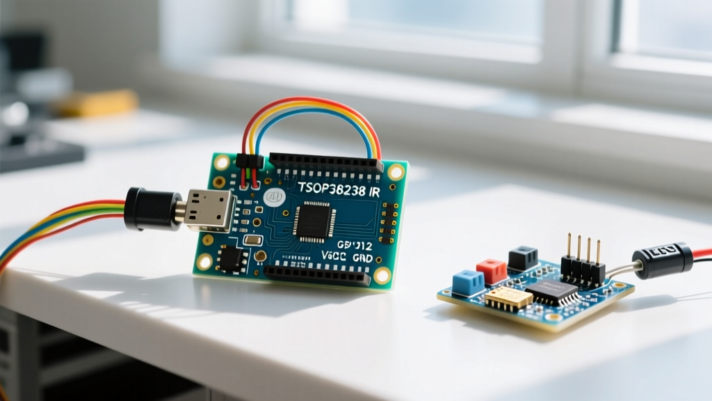
| TSOP38238 (Vishay) | $1.20 - $1.60 | 38kHz | Excellent | Commercial, outdoor, high-noise environments |
| TSOP57238 (SMD) | $1.80 - $2.20 | 38kHz | Superior | Custom PCBs, ultra-compact wearables |
Source data aligned with Vishay IR Receiver specifications and major distributor pricing.
The Mandatory RC Filter
When wiring a bare TSOP38238 or VS1838B (not the pre-mounted KY-022 sensor board), you must decouple the power supply. The internal AGC (Automatic Gain Control) of the receiver will ramp up sensitivity if it detects voltage ripple, causing it to lock onto phantom signals.
- Resistor: Place a 100Ω to 220Ω resistor in series with the VCC line.
- Capacitor: Place a 4.7µF to 10µF electrolytic capacitor directly across the VCC and GND pins of the receiver, after the resistor.
- Pull-up: The data pin is open-drain. Use the Arduino's internal pull-up via code, or add an external 10kΩ pull-up resistor to VCC for longer wire runs (over 1 meter).
Step-by-Step IRremote Arduino Configuration
Assuming you are using the Arduino IDE or PlatformIO, install the latest version of the IRremote library via the Library Manager. Below is the modern, optimized configuration for both receiving and transmitting.
1. Receiver Initialization (v4.x Syntax)
The legacy irrecv.enableIRIn() is deprecated. The new object-oriented approach requires you to call begin() on the IrReceiver instance. You can also map a feedback LED to blink on signal reception, which is invaluable for debugging hardware wiring without a serial monitor.
#include <IRremote.hpp>

const uint8_t IR_RECEIVE_PIN = 2;
const uint8_t LED_FEEDBACK_PIN = 13;

void setup() {
    Serial.begin(115200);
    // Initialize receiver with LED feedback enabled
    IrReceiver.begin(IR_RECEIVE_PIN, ENABLE_LED_FEEDBACK, LED_FEEDBACK_PIN);
    Serial.println("IR Receiver configured for 38kHz NEC/Sony/RC5.");
}

void loop() {
    if (IrReceiver.decode()) {
        // Print a short summary of the decoded data
        IrReceiver.printIRResultShort(&Serial);

        // Accessing the decoded hex value (v4.x syntax)
        uint32_t command = IrReceiver.decodedIRData.command;
        uint16_t address = IrReceiver.decodedIRData.address;

        Serial.print("Address: "); Serial.println(address, HEX);
        Serial.print("Command: "); Serial.println(command, HEX);

        // CRITICAL: Resume receiving after processing
        IrReceiver.resume();
    }
}
2. Transmitter Setup and Carrier Frequency
Transmitting requires an IR LED (typically 940nm) driven by an NPN transistor (like a 2N2222) to handle the 100mA+ pulse currents. Do not drive an IR LED directly from an Arduino GPIO; the 40mA absolute maximum limit will degrade the microcontroller over time.
#include <IRremote.hpp>

const uint8_t IR_SEND_PIN = 3; // Must be a PWM-capable pin

void setup() {
    Serial.begin(115200);
    IrSender.begin(IR_SEND_PIN, ENABLE_LED_FEEDBACK);
}

void loop() {
    // Send NEC Power Code (Address: 0x04, Command: 0x08)
    IrSender.sendNEC(0x04, 0x08, 2); // 2 repeats
    delay(2000);
}
Decoding Protocols: NEC, Sony, and RC5
The IRremote library automatically attempts to decode incoming 38kHz bursts into known protocols. However, understanding the underlying architecture helps when dealing with edge cases.
Expert Insight: The NEC protocol uses pulse-distance encoding and is the most common for Asian-market consumer electronics. Sony SIRCS uses pulse-width encoding. If your device uses a proprietary protocol (like many modern Dyson fans or specialized HVAC units), the library will outputUNKNOWN. In this scenario, you must capture the raw timing data usingIrReceiver.compensateAndPrintIRResultAsCArray(&Serial)and re-transmit it using thesendRaw()function.
Protocol Identification Matrix
- NEC: 32 bits. Identifiable by a 9ms leading pulse burst and 4.5ms space. Highly robust due to inverted 16-bit address verification.
- Sony SIRCS: 12, 15, or 20 bits. Identifiable by a 2.4ms start pulse. Lacks address verification, making it prone to accidental triggers from random IR noise.
- RC5 / RC6 (Philips): Uses Manchester encoding. Requires the library to track the mid-bit transitions. Excellent for multi-device environments as it includes a toggle bit to differentiate between a held button and repeated presses.
Edge Cases and Advanced Troubleshooting
Even with perfect wiring, environmental and architectural factors can disrupt your IRremote Arduino setup. Here is how to solve the most persistent issues encountered in professional maker spaces.
1. Fluorescent and LED Driver Interference
CFL bulbs and cheap PWM-driven LED strips emit broadband optical noise, often peaking near 38kHz. This causes the VS1838B's AGC to max out its gain, rendering it "deaf" to your remote. Solution: Switch to a Vishay TSOP38238, which features an integrated bandpass filter and a specialized AGC algorithm designed specifically to suppress continuous 38kHz noise. Alternatively, physically shield the receiver with a darkened acrylic filter (e.g., Lee Filters #158) that blocks visible light but passes 940nm IR.
2. ESP32 Timer and Wi-Fi Jitter
When migrating an IRremote project from an ATmega328P to an ESP32, you may notice severe decoding jitter or missed frames. The ESP32's Wi-Fi and Bluetooth stacks utilize hardware interrupts that can preempt the microsecond-level timer interrupts required by the IRremote library to measure pulse widths.
Solution:
1. Ensure you are using the latest ESP32 Arduino Core.
2. In the IRremote library's IRremote.h or via build flags, verify that the library is assigned to a hardware timer that does not conflict with your project's PWM or servo libraries.
3. For mission-critical HVAC or security projects, pin the IR decoding task to Core 1, while leaving Wi-Fi operations on Core 0 using FreeRTOS task pinning.
3. The "Held Button" Repeat Code Anomaly
A common logical error occurs when users hold a button on an IR remote. The NEC protocol sends the full 32-bit code once, followed by a specific REPEAT frame (0xFFFFFFFF) every 108ms. If your code only checks for the specific command hex, it will ignore the repeat frames, causing your motor or LED to stutter rather than run smoothly. Solution: Check the IrReceiver.decodedIRData.flags variable. If IRDATA_FLAGS_IS_REPEAT is set, treat it as a continuation of the previous command.
Final Calibration Checklist
Before finalizing your enclosure, run this 4-point checklist to ensure long-term reliability:
- Optical Alignment: Verify the IR LED emission cone (usually ±20 degrees) overlaps with the receiver's acceptance angle at your maximum operational distance.
- Voltage Sag Test: Monitor the VCC rail with an oscilloscope during IR transmission. A drop below 4.5V on a 5V system indicates inadequate power delivery, which will shift the 38kHz carrier frequency and cause receiver rejection.
- Timeout Logic: Implement a software timeout in your
loop(). If an IR signal is lost due to a user walking out of range, your device must safely revert to a default state rather than remaining locked in the last received command. - Memory Leaks: Avoid using
Stringobjects when formatting IR hex codes for serial output or Wi-Fi payloads. Usesnprintf()with character arrays to prevent heap fragmentation during long-term operation.
By respecting the hardware physics of IR light and adhering to the modern v4.x library architecture, your IRremote Arduino configuration will deliver commercial-grade responsiveness and reliability.