
The Arduino and Sound Bottleneck: Why Workflows Matter
When makers first explore arduino and sound projects, the typical workflow involves dropping a WAV file onto an SD card and calling a basic library like TMRpcm. While this works for simple beeps or low-fidelity voice prompts, it quickly falls apart in professional or complex maker environments. You encounter SD card read latency, SRAM buffer underruns, PWM carrier noise, and blocking code that starves your main application loop.
Optimizing your audio workflow requires shifting from a "plug-and-play" mindset to a systems-engineering approach. This means matching the right digital-to-analog conversion (DAC) topology to your microcontroller's architecture, pre-processing audio assets to minimize runtime CPU overhead, and implementing non-blocking, interrupt-driven playback. In 2026, with the ubiquity of high-memory ESP32-S3 boards and advanced I2S amplifiers, there is no excuse for glitchy, low-fidelity microcontroller audio.
Hardware Topology Matrix: PWM vs. SPI DAC vs. I2S
Before writing a single line of code, you must select the correct hardware interface. Your choice dictates your memory workflow, CPU overhead, and analog filtering requirements. Below is a decision matrix for modern MCU audio projects.
| Method | Hardware Example | Resolution | CPU Overhead | Workflow Complexity | Best Use Case |
|---|---|---|---|---|---|
| Hardware PWM | ATmega328P Timer1 | 8-bit to 10-bit | High (Interrupts) | High (Requires analog filtering) | Simple voice prompts, low-cost legacy boards |
| SPI DAC | MCP4922 ($2.15) | 12-bit | Medium (SPI transfers) | Medium (Requires external op-amp) | Synthesizers, precise waveform generation |
| I2S Bus | MAX98357A ($4.50) | 16-bit to 24-bit | Ultra-Low (DMA) | Low (Direct to speaker) | High-fidelity music, ESP32 streaming |
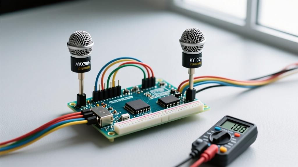
For any new project requiring high-fidelity playback, I2S is the undisputed standard. The MAX98357A combines an I2S receiver and a Class-D amplifier in a single 3x3mm QFN package, outputting up to 3.2W directly to a 4Ω speaker. It completely bypasses the CPU by utilizing Direct Memory Access (DMA), freeing your microcontroller to handle WiFi, sensor fusion, or UI rendering simultaneously.
Phase 1: The Asset Pre-Processing Pipeline
The most common point of failure in MCU audio is attempting to play standard 44.1kHz stereo CD-quality WAV files. Microcontrollers do not have the bus speed or RAM to decode and stream this natively without aggressive buffering. You must shift the computational burden from the microcontroller to your development machine using a pre-flight asset pipeline.
The FFmpeg Standardization Script
Stop using GUI audio editors for batch processing. Integrate FFmpeg and sample rate conversion tools into your build script. For an ATmega328P or basic ESP8266 project, convert all audio to 16kHz, Mono, 16-bit Signed Raw PCM.
ffmpeg -i input_audio.wav -ar 16000 -ac 1 -sample_fmt s16 -f s16le output.rawWhy this specific format? At 16kHz mono 16-bit, one second of audio consumes exactly 32KB. This fits perfectly into the flash memory constraints of larger AVRs or can be easily streamed in 512-byte chunks from an SPI Flash chip. By stripping the WAV header and outputting raw PCM (s16le), you eliminate the need for the MCU to parse RIFF headers at runtime, saving precious boot time and code space.
Phase 2: Memory Management and Buffering Strategies
Audio data is inherently bulky. Managing where this data lives is the crux of the Arduino Memory Guide and advanced MCU architectures.
The ATmega328P PROGMEM Workflow
The ATmega328P has a mere 2KB of SRAM. You cannot load audio into RAM. Instead, embed the raw PCM array directly into the 32KB Flash memory using the PROGMEM attribute.
const int16_t audio_data[] PROGMEM = { 0x0012, -0x04A2, 0x11B3 ... };During playback, you must fetch samples using pgm_read_word_near(). This workflow is strictly limited to short sound effects (under 0.8 seconds at 16kHz).
The ESP32-S3 PSRAM Paradigm
If your project requires multi-minute audio or simultaneous sound mixing, migrate to the ESP32-S3. Modern ESP32-S3-WROOM-1 modules ($6.00 - $8.00) feature 8MB of Octal PSRAM. By leveraging the Espressif I2S Peripheral Documentation, you can configure the I2S driver to pull directly from PSRAM via DMA, completely bypassing the internal 512KB SRAM bottleneck.
Phase 3: Interrupt-Driven Execution vs. Blocking Loops
Amateur audio workflows rely on blocking while() loops with delayMicroseconds(). This introduces catastrophic timing jitter, resulting in audible distortion and pitch shifting. Furthermore, it halts all other MCU operations.
Implementing Timer1 CTC Mode (AVR)
For PWM or SPI DAC workflows on AVR boards, you must use hardware timers. Configure Timer1 in Clear Timer on Compare Match (CTC) mode. To achieve a 16kHz sample rate, the interrupt must fire every 62.5µs.
- Prescaler: Set to 8 (yielding a 2MHz timer clock on a 16MHz board).
- OCR1A Value: Set to 124. (2,000,000 / 125 = 16,000 Hz).
- ISR Routine: Keep the Interrupt Service Routine under 10 clock cycles. Read one sample from PROGMEM, write to the DAC/PWM register, and increment the pointer. Do not perform math inside the ISR.
ESP32 DMA and the ESP8266Audio Library
For ESP-based boards, do not write your own I2S DMA buffers unless absolutely necessary. The industry-standard ESP8266Audio GitHub Repository (which fully supports ESP32) abstracts the DMA buffer management, I2S clock generation, and SD card streaming into highly optimized, non-blocking C++ classes. Utilizing this library reduces development time from weeks to hours while ensuring bit-perfect timing.
Real-World Failure Modes and Edge Cases
Even with perfect code, analog physics will ruin your audio if you ignore the hardware edge cases. Here are the most common failure modes and their engineered solutions:
Failure Mode 1: PWM Carrier Frequency WhineIf using AVR PWM (default 490Hz or 980Hz), the carrier frequency falls squarely in the human hearing range, creating a loud, high-pitched whine.
Solution: Reconfigure Timer1 to operate in Phase and Frequency Correct PWM mode with no prescaler, pushing the carrier frequency to 62.5kHz. Follow this with a 2nd-order LC low-pass filter (e.g., 10µH inductor, 100nF capacitor) to attenuate the ultrasonic carrier before it reaches the amplifier.
Failure Mode 2: Digital Ground Loop HumMicrocontroller digital switching noise couples into the analog ground plane, manifesting as a 50/60Hz hum or high-frequency hash in the speaker.
Solution: Implement a strict star-ground topology. Alternatively, use a digital isolator (like the TI ISO7741) between the MCU's I2S/SPI lines and the external DAC, completely breaking the galvanic ground connection.
Failure Mode 3: I2S Clock Drift and PoppingWhen streaming audio over WiFi (e.g., DLNA or Spotify Connect), network jitter causes the I2S DMA buffer to underrun, resulting in loud, speaker-damaging pops.
Solution: Implement a circular buffer with a "watermark" threshold. Do not start the I2S DMA stream until the buffer is at least 40% full. If the buffer drops below 15%, gracefully mute the DAC via its shutdown pin rather than feeding garbage data to the speaker.
Summary: The Optimized Audio Pipeline
Mastering arduino and sound requires treating audio not as an afterthought, but as a high-throughput data pipeline. By standardizing your asset conversion via FFmpeg, selecting I2S topologies with DMA support, and isolating your analog stages from digital noise, you elevate your projects from hobbyist novelties to robust, commercial-grade audio devices. Stop fighting SRAM limits and blocking code; let the hardware peripherals handle the heavy lifting.