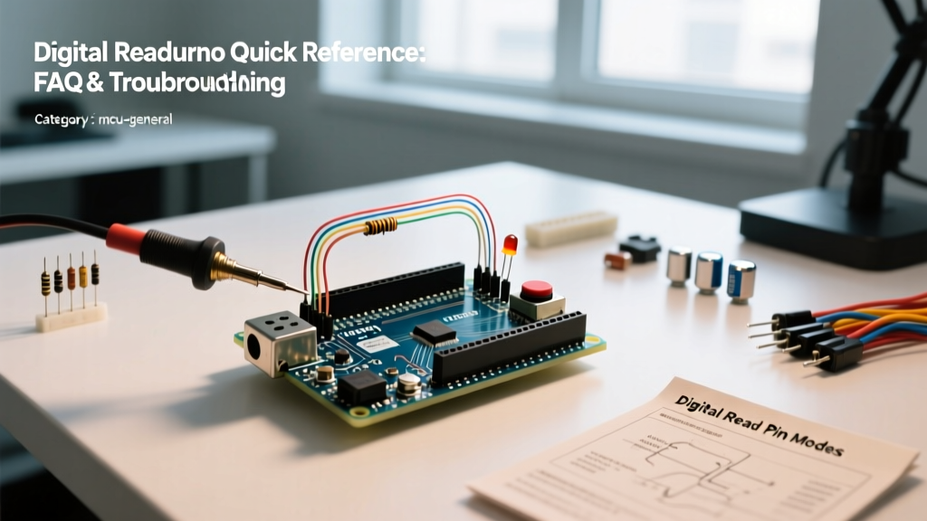

The Ultimate Quick Reference for Digital Read Arduino
The digitalRead() function is one of the most fundamental operations in embedded systems, allowing microcontrollers to detect binary states (HIGH or LOW) from switches, sensors, and logic circuits. Whether you are building a simple button interface or integrating complex 5V logic with modern 3.3V microcontrollers, mastering the digital read Arduino workflow is essential for reliable hardware design.
This quick reference guide and FAQ bypasses the basic tutorials and dives straight into edge cases, hardware-level troubleshooting, and advanced implementation details for boards ranging from the classic ATmega328P (Uno) to the RP2040 (Raspberry Pi Pico) and ESP32.
Core Syntax and Execution Cheat Sheet
| Parameter | Details & Specifications |
|---|---|
| Syntax | digitalRead(pin) |
| Parameters | pin: The number of the digital pin you want to read (e.g., 2, 13, A0). |
| Returns | HIGH (1) or LOW (0) |
| Execution Time | ~3.2 µs on 16MHz ATmega328P; ~0.5 µs on RP2040 (133MHz). |
| Default Pin Mode | INPUT (High impedance, floating state if unconfigured). |
Frequently Asked Questions (FAQ)
1. Do I strictly need to call pinMode() before using digitalRead()?
Technically, the microcontroller defaults to INPUT mode on boot, meaning digitalRead() will execute without a prior pinMode() declaration. However, best practice dictates you always explicitly define your pin modes. Relying on defaults leads to floating pins if the hardware resets unexpectedly. Furthermore, if you want to use the internal pull-up resistor, you must use pinMode(pin, INPUT_PULLUP), which activates an internal resistor (typically 20kΩ to 50kΩ on the ATmega328P, and 50kΩ to 60kΩ on the RP2040) to tie the pin to VCC, preventing floating states when a switch is open.
2. Why is my digital read Arduino pin returning random HIGH/LOW values?
If your serial monitor shows a chaotic stream of 1s and 0s when a button is unpressed, your pin is 'floating.' A floating pin acts as a high-impedance antenna, picking up electromagnetic interference (EMI), 60Hz mains hum, and radio frequencies.
- Hardware Fix: Add an external 10kΩ pull-down resistor (to GND) or 10kΩ pull-up resistor (to VCC).
- Software Fix: Use
INPUT_PULLUPin your setup function. Note that this inverts your logic: an unpressed button readsHIGH, and a pressed button (connected to GND) readsLOW.
3. Can I read a 5V sensor signal on a 3.3V board like the ESP32?
WARNING: Never connect a 5V digital output directly to a 3.3V microcontroller pin. Doing so will exceed the absolute maximum ratings of the GPIO input protection diodes, leading to permanent silicon degradation or immediate failure.
Many legacy sensors (like the HC-SR501 PIR motion sensor) output 5V logic. To safely perform a digital read Arduino-style on a 3.3V MCU, you must step down the voltage.
- Low-Cost Method: Use a voltage divider. A 2kΩ resistor in series with a 3.3kΩ resistor to GND will safely drop 5V down to ~3.0V, which registers as a valid
HIGHon 3.3V logic (V_IH threshold is typically 0.75 * VDD). - High-Speed Method: Use a dedicated logic level shifter IC like the TXB0108 or a simple hex buffer like the CD4050B for frequencies above 100kHz.
4. Can I use analog pins (A0-A5) for digital reads?
Yes. On the standard Arduino Uno (ATmega328P), the analog pins A0 through A5 double as standard digital pins numbered 14 through 19. You can safely call digitalRead(A0) or digitalRead(14). The Arduino core handles the mapping automatically. However, on newer architectures like the ESP32, GPIO mapping is entirely different, and pins labeled 'ADC' or 'Touch' must be referenced by their specific GPIO numbers (e.g., GPIO34 is input-only and lacks internal pull-ups).
Deep Dive: Solving Switch Bounce in Digital Reads
Mechanical switches and relays do not make perfect electrical contact instantly. When contacts close, they physically 'bounce' against each other for 1 to 5 milliseconds before settling. To a microcontroller executing millions of instructions per second, a single button press looks like dozens of rapid HIGH/LOW transitions. If you are counting button presses or triggering state changes, this bounce will cause erratic behavior.
While hardware debouncing using an RC low-pass filter (e.g., 10kΩ resistor and 100nF capacitor) paired with a 74HC14 Schmitt Trigger is ideal for electrically noisy industrial environments, software debouncing is usually sufficient for maker projects.
Below is a non-blocking debounce implementation using millis(), which avoids the dreaded delay() function that halts your entire program. For the foundational theory on switch contact physics, see Jack Ganssle's authoritative guide to debouncing.
const int buttonPin = 2;
int buttonState;
int lastButtonState = LOW;
unsigned long lastDebounceTime = 0;
unsigned long debounceDelay = 50; // 50ms debounce window

void setup() {
  pinMode(buttonPin, INPUT_PULLUP);
  Serial.begin(115200);
}

void loop() {
  int reading = digitalRead(buttonPin);

  // Check if state changed and reset timer
  if (reading != lastButtonState) {
    lastDebounceTime = millis();
  }

  // If state is stable longer than debounceDelay
  if ((millis() - lastDebounceTime) > debounceDelay) {
    if (reading != buttonState) {
      buttonState = reading;
      // Action triggers only on stable state change
      if (buttonState == LOW) { // LOW because of INPUT_PULLUP
        Serial.println('Button Pressed!');
      }
    }
  }
  lastButtonState = reading;
}
Troubleshooting Matrix: Common digitalRead() Failures
Use this diagnostic matrix to quickly isolate hardware and software faults when your digital read Arduino circuit fails to respond as expected.
| Symptom | Probable Cause | Actionable Fix |
|---|---|---|
Pin always reads HIGH, even when button is pressed. |
Wiring error; button is not completing the circuit to GND, or using INPUT_PULLUP without wiring the switch to GND. |
Verify continuity with a multimeter. Ensure one side of the switch is connected to the GPIO pin and the other directly to GND. |
Pin reads LOW continuously. |
Short circuit to GND, or the pin is being driven by an external 5V source while configured as an output low. | Disconnect external circuits. Check for solder bridges on custom PCBs or loose jumper wires touching the ground rail. |
| Readings are stable but inverted (HIGH when open, LOW when closed). | Using INPUT_PULLUP logic without adjusting the conditional statements in the code. |
Change your if (state == HIGH) condition to if (state == LOW), or wire an external pull-down resistor and use standard INPUT. |
| Erratic readings only when a motor or relay switches on. | Electromagnetic Interference (EMI) or voltage brownout on the 5V rail causing logic threshold violations. | Add a 100nF ceramic decoupling capacitor across the sensor's VCC and GND pins. Route signal wires away from high-current motor lines. |
digitalRead() on an ESP32 pin always returns 0. |
Attempting to use GPIO34, 35, 36, or 39 as an input with a pull-up. These are input-only pins and lack internal pull-up resistors. | Move the signal to a standard GPIO (e.g., GPIO4) or add an external 10kΩ pull-up resistor to the 3.3V rail. |
Summary and Best Practices
Reliable digital inputs are the backbone of interactive electronics. Always explicitly define your pinMode, respect the logic voltage thresholds of your specific microcontroller architecture, and implement debouncing for any mechanical contact. For official syntax documentation and core library updates, always refer to the official Arduino Language Reference. By combining proper hardware biasing with non-blocking software techniques, your digital read Arduino projects will achieve industrial-level reliability.