
The Reality of Off-Grid MCU Power
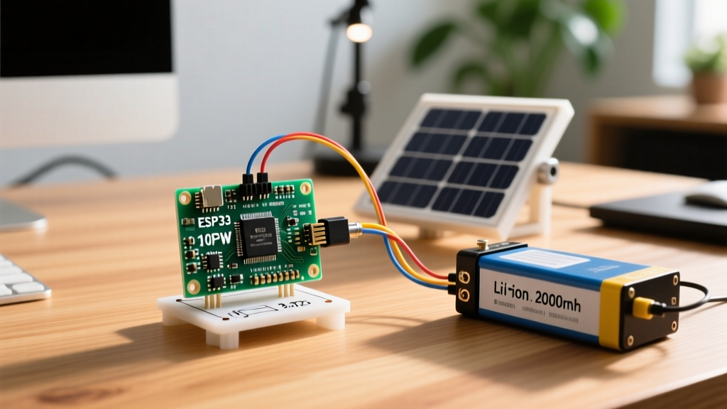
Deploying a microcontroller in the field for environmental monitoring, agricultural tracking, or remote telemetry introduces a harsh reality: wall outlets do not exist in nature. While standard alkaline or lithium primary batteries can power a basic sensor node for a few weeks, long-term autonomous operation requires harvesting ambient energy. Building a robust arduino solar panel system is the most reliable method for achieving true off-grid permanence. However, simply wiring a photovoltaic cell to a battery and an MCU is a recipe for system failure, over-discharged cells, and fried voltage regulators.
In this comprehensive 2026 guide, we will engineer a complete, weather-resilient solar power subsystem tailored for low-power Arduino architectures (such as the 3.3V ATmega328P Pro Mini or the Arduino Nano 33 IoT). We will cover exact component selection, power budget mathematics, step-by-step wiring, and the critical firmware optimizations required to survive multi-day weather events.
Sizing Your Arduino Solar Panel Array
The most common mistake makers make is undersizing the photovoltaic array based on 'ideal laboratory conditions.' To size your system correctly, you must calculate your daily energy consumption in milliamp-hours (mAh) and compare it against the Peak Sun Hours (PSH) in your specific geographic location. According to the National Renewable Energy Laboratory (NREL), PSH varies drastically by season and latitude. A location that receives 5.5 PSH in July might drop to 2.1 PSH in December.
The Golden Rule of Solar Sizing: Your solar array must generate at least 30% more energy during the worst-case winter month than your system consumes daily. This buffer accounts for panel degradation, dust accumulation, and consecutive overcast days.
Power Budget Calculation
Assume we are running a soil moisture sensor node using an ATmega328P (8MHz, 3.3V) and a LoRaWAN radio module. By utilizing deep sleep modes, our power budget looks like this:
- Active State (Sensing & TX): 65 mA for 4 seconds, triggered every 30 minutes. (Total: 13.8 mAh/day)
- Deep Sleep State: 0.08 mA for the remaining 23.8 hours. (Total: 1.9 mAh/day)
- Total Daily Consumption: ~15.7 mAh/day.
To generate 15.7 mAh in a worst-case winter scenario of 2.0 PSH, we need a panel capable of delivering at least 7.85 mA continuously during peak sun. A standard 6V 3W Monocrystalline Panel produces roughly 500 mA at peak, yielding 1000 mAh in 2.0 PSH—more than enough to sustain our 15.7 mAh daily load and recharge a depleted battery bank after a storm.
Essential Hardware BOM (2026 Edition)
Component selection dictates the efficiency of your charge cycle. Linear regulators waste excess voltage as heat; therefore, we utilize specialized solar charge management ICs. Below is the exact Bill of Materials for a bulletproof deployment.
| Component | Specific Model / Part Number | Est. Price (2026) | Purpose |
|---|---|---|---|
| Solar Panel | 6V 3.5W Monocrystalline (Epoxy or PET) | $14.00 - $18.00 | Energy harvesting; 6V nominal matches Li-ion charge curves. |
| Charge Controller | Adafruit bq24074 Breakout (ID: 3898) | $14.95 | Manages dynamic power path, prevents battery overcharge/over-discharge. |
| Battery | Samsung 35E 18650 (3500mAh) + Holder | $9.50 | High-density energy storage; 5+ days of autonomy without sun. |
| MCU | SparkFun Pro Mini 3.3V (8MHz) | $12.00 | Low-power microcontroller (requires onboard LED & regulator removal). |
| Schottky Diode | BAT85 or 1N5817 | $0.10 | Prevents reverse current flow from battery to panel at night. |
Step-by-Step Wiring Guide
The Adafruit bq24074 breakout is the heart of this system. It features Dynamic Power Path Management, meaning it will simultaneously power the Arduino and charge the battery when the sun is shining, and seamlessly switch to battery power when darkness falls.
- Panel to Charge Controller: Solder the positive (red) wire of your 6V solar panel to the
VINpad on the bq24074. Solder the negative (black) wire to theGNDpad. Crucial: If your panel lacks a built-in blocking diode, solder a 1N5817 Schottky diode in series with the positive wire (cathode facing the charger) to prevent nighttime reverse leakage. - Battery Connection: Insert the Samsung 35E 18650 into a high-quality spring-loaded battery holder. Wire the holder's positive terminal to the
BATpad and the negative toGND. Ensure your solder joints are thick (18 AWG wire recommended) to handle the charging current without voltage drop. - Load Output to Arduino: The bq24074 outputs a regulated voltage on the
OUTpins. However, this voltage fluctuates between 4.2V (fully charged) and 3.3V (depleted). Because the 3.3V Pro Mini requires a stable input, wire theOUTpositive to theRAW(orVCC) pin on the Arduino, andGNDtoGND. The Pro Mini's onboard MCP1700 LDO will handle the final regulation to 3.3V. - Current Limit Setting: The bq24074 has an
ISETresistor. By default, it is configured for a 1.5A charge current. For a 3W panel and a single 18650 cell, you must replace the surface-mount resistor with a 2.0 kΩ resistor to limit the charge current to ~500mA, preventing battery degradation and panel voltage collapse.
Firmware: Slashing Current Draw with Deep Sleep
Hardware is only half the battle. If your Arduino sketch uses delay(), the MCU remains fully active, drawing 15-20mA continuously. To achieve the 0.08mA sleep current calculated in our budget, you must utilize hardware interrupts and the watchdog timer.
Using the official Arduino low-power methodologies alongside the Rocket Scream LowPower library, you can shut down the ADC, Brown-Out Detector (BOD), and CPU clocks.
#include 'LowPower.h'

void setup() {
  // Disable ADC to save ~1mA
  ADCSRA = 0;
}

void loop() {
  // 1. Wake up and read sensors (Code omitted for brevity)
  readSoilMoisture();
  transmitLoRaData();

  // 2. Enter deep sleep for 8 seconds
  // Repeat this 112 times to sleep for roughly 15 minutes
  for (int i = 0; i < 112; i++) {
    LowPower.powerDown(SLEEP_8S, ADC_OFF, BOD_OFF);
  }
}
Pro-Tip: The Brown-Out Detector (BOD) prevents the MCU from executing corrupted code during voltage drops, but it consumes roughly 20µA continuously. Disabling it via fuse bits or software macros during sleep is mandatory for microamp-level efficiency.
Real-World Failure Modes and Edge Cases
Even with perfect wiring and optimized code, environmental edge cases will destroy poorly planned deployments. Anticipate these specific failure modes:
1. The Freezing Temperature Trap (Lithium Plating)
Lithium-ion chemistry fundamentally breaks down if charged at or below freezing (0°C / 32°F). Forcing current into a cold 18650 cell causes 'lithium plating' on the anode, which permanently reduces capacity and creates internal dendrites that can short the cell and cause a fire. The bq24074 does not feature an external NTC thermistor pin to suspend charging in cold weather. If you are deploying in alpine or northern winter environments, you must either insulate and heat the battery enclosure using a fraction of your harvested power, or upgrade to a charge controller like the Texas Instruments bq25180 which supports cold-temperature charge suspension.
2. Panel Voltage Collapse Under Load
A '6V' solar panel actually has an Open Circuit Voltage (Voc) of roughly 7.2V to 9V. When a depleted battery demands maximum current, the panel's voltage can collapse below the bq24074's Under-Voltage Lockout (UVLO) threshold, causing the IC to rapidly reboot and enter a 'hiccup' mode where it charges for milliseconds, stops, and repeats. To fix this, ensure your panel's wattage is at least 1.5x the maximum charge current required by the battery, or add a 1000µF low-ESR capacitor across the VIN and GND terminals to buffer transient voltage dips.
3. The 'Vampire' Draw of Onboard Regulators
If you use a standard Arduino Uno or Nano for a solar project, you will fail. The onboard USB-to-Serial converter (ATmega16U2) and the standard 5V linear regulators draw a quiescent 'vampire' current of 10mA to 25mA, even when the main MCU is asleep. Always use raw boards like the Pro Mini, or physically desolder the power LED and onboard voltage regulators from your development board before deploying it to the field.
Field Engineer's Note: Always coat your exposed solder joints and charge controller breakout boards in a conformal silicone coating (such as MG Chemicals 419D) before placing them in an IP67 enclosure. Condensation inside a sealed enclosure due to diurnal temperature swings will bridge the high-impedance ISET pins and corrupt the charge cycle.