
The Direct Answer: Flash vs. SRAM
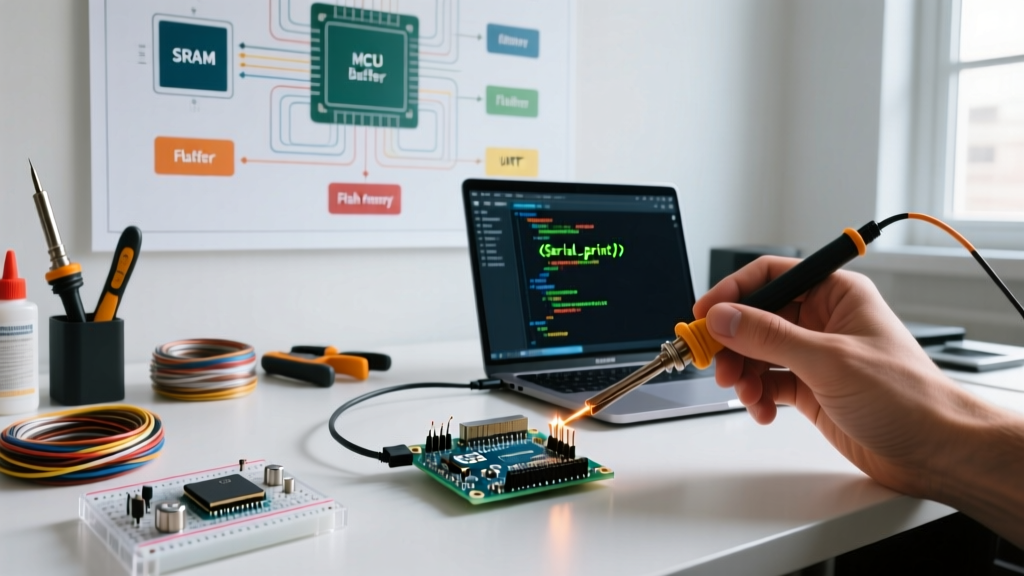
When embedded engineers and makers ask where is Arduino Serial.print stored, the question actually addresses two distinct phases of data handling. The short answer is that your data exists in two places simultaneously: the string literals are stored in non-volatile Flash memory (PROGMEM), while the active transmission bytes are temporarily held in a volatile hardware UART transmit buffer located in SRAM.
Understanding this dual-storage mechanism is critical for cross-board compatibility. A sketch that runs flawlessly on an ATmega328P-based Arduino Uno might crash an ESP32 or RP2040 board if the developer misunderstands how different microcontroller architectures manage their SRAM ring buffers and hardware FIFOs. This compatibility guide breaks down exactly how Serial.print() utilizes memory across the most popular 2026 maker architectures.
The Golden Rule of Serial Storage: Flash memory holds the blueprint (your code and static strings). SRAM holds the active workload (the transmit buffer). If your SRAM buffer overfills faster than the baud rate can drain it, your microcontroller will block execution or drop packets.
The Two-Step Storage Mechanism
Step 1: The String Literal (Flash Memory)
When you write Serial.print("Sensor Reading:");, the text "Sensor Reading:" is compiled into the microcontroller's Flash memory. On 8-bit AVR chips (like the Uno or Mega), Flash is Harvard-architected, meaning it is physically separate from SRAM. On 32-bit ARM and Xtensa chips (SAMD21, ESP32, RP2040), Flash is memory-mapped, allowing the CPU to read string literals directly from Flash without explicitly copying them to SRAM first.
Step 2: The Transmit Buffer (SRAM)
When the print() function executes, the Arduino core API fetches the characters and pushes them into a software ring buffer located in SRAM. This buffer acts as a waiting room. A hardware interrupt service routine (ISR) or a background FreeRTOS task then pulls bytes from this SRAM buffer one by one and pushes them into the hardware UART FIFO to be shifted out electrically via the TX pin.
Architecture Compatibility Matrix
Migrating code between architectures requires understanding how different cores allocate SRAM for the Serial object. Below is a compatibility matrix detailing default buffer sizes and architectural quirks for mainstream development boards.
| Microcontroller | Common Board | Software TX Buffer (SRAM) | Hardware UART FIFO | Core Architecture & Behavior |
|---|---|---|---|---|
| ATmega328P (8-bit AVR) | Arduino Uno R3 | 64 Bytes | 1 Byte (UDR) | Blocks execution if buffer fills. Defined by SERIAL_TX_BUFFER_SIZE. |
| SAMD21 (32-bit ARM) | Arduino Zero / Nano 33 IoT | 256 Bytes | 1 Byte (DATA) | Uses RingBuffer class. Faster drain due to higher clock speeds. |
| ESP32 (Xtensa LX6/LX7) | ESP32 DevKit V1 / S3 | 128 Bytes (Default) | 128 Bytes | Managed by FreeRTOS. Background tasks handle UART draining independently of the main loop. |
| RP2040 (Dual ARM M0+) | Raspberry Pi Pico | 256 Bytes | 32 Bytes | Earle Philhower's core utilizes PIO or hardware UART with deep FIFOs and DMA support. |
Deep Dive: SRAM Buffers, Baud Rates, and Blocking
To truly master where your data is stored, you must understand the relationship between SRAM buffer size and baud rate. The baud rate dictates how fast the hardware drains the SRAM buffer.
Consider an Arduino Uno transmitting at 9600 baud. Because UART requires 10 bits per byte (1 start, 8 data, 1 stop), the transmission rate is 960 bytes per second. This means a single byte takes approximately 1.04 milliseconds to transmit. If the default 64-byte SRAM buffer is completely full, it will take roughly 66.5 milliseconds to drain entirely.
If your loop() attempts to push more than 64 bytes into the buffer within that 66.5ms window, the Serial.print() function will block. The microcontroller will pause your code, trapping it in a while loop inside the HardwareSerial.cpp file until space frees up in SRAM. This is a common cause of timing failures in robotics and PID control loops.
Preventing Buffer Overflow with availableForWrite()
Rather than guessing if your SRAM buffer has space, modern Arduino cores provide a built-in method to query the exact available storage in the transmit buffer:
if (Serial.availableForWrite() >= 20) {
  Serial.print("Sensor Value: ");
  Serial.println(analogRead(A0));
}
According to the official Arduino Serial Reference, availableForWrite() returns the number of bytes currently empty in the TX buffer, allowing for non-blocking telemetry design.
The F() Macro: Legacy AVR vs Modern 32-Bit Cores
Historically, 8-bit AVR developers used the F() macro to force string literals to stay in Flash memory. Without F(), older AVR-GCC compilers would copy string literals into SRAM during the boot sequence, wasting precious RAM.
// Legacy AVR optimization
Serial.print(F("This string stays in Flash memory."));
Is the F() macro still required in 2026? For 32-bit architectures like the ESP32 and RP2040, the F() macro is essentially ignored by the compiler. As detailed in the Espressif UART API documentation, 32-bit chips utilize memory-mapped Flash, meaning string literals are inherently read directly from Flash without consuming SRAM. However, if you are writing a library that must maintain backward compatibility with 8-bit AVR boards, wrapping your static strings in F() remains a mandatory best practice.
Hardware Serial vs. Software Serial Storage
When hardware UART pins are unavailable, developers often fall back to SoftwareSerial. The storage mechanism here is drastically different and heavily impacts compatibility.
- Hardware Serial: Relies on dedicated silicon peripherals. The CPU only interrupts to move a byte from the SRAM ring buffer to the hardware FIFO. CPU overhead is less than 2%.
- Software Serial: The microcontroller's CPU must manually toggle a GPIO pin high and low using precise microsecond delays to simulate a UART signal. The SRAM buffer still exists, but the CPU overhead to drain it can exceed 90% at high baud rates, effectively starving your main
loop()of processing time.
For modern designs using the RP2040, developers should avoid SoftwareSerial entirely. The Raspberry Pi Pico SDK hardware UART group and the PIO (Programmable I/O) state machines allow you to route hardware-level UART signals to almost any GPIO pin without CPU intervention, preserving both SRAM and processing cycles.
Troubleshooting Edge Cases in Telemetry Storage
When building high-speed data loggers, understanding buffer limits prevents silent data corruption. Here are specific edge cases to watch for:
1. The ESP32 FreeRTOS Queue Bottleneck
On the ESP32, the Arduino core runs on top of FreeRTOS. The UART driver utilizes an internal FreeRTOS queue to pass data from the API to the background task. If you flood Serial.print() with high-frequency IMU data at 2,000,000 baud, the FreeRTOS queue can overflow, resulting in dropped bytes rather than a hard system crash. To fix this, increase the baud rate to match the physical limits of the USB-to-UART bridge (e.g., CP2102 or CH340), or implement a software-level ring buffer in your sketch before passing data to Serial.
2. RP2040 PIO UART Buffer Overruns
When using the Raspberry Pi Pico's PIO to create additional serial ports, the hardware FIFO is only 4 bytes deep per state machine. The Arduino-Pico core implements a 256-byte software buffer in SRAM to compensate. However, if interrupts are disabled for extended periods (e.g., during direct WS2812 LED strip writes via NeoPixel libraries), the PIO FIFO will overrun, and data stored in the SRAM buffer will fail to transfer to the hardware layer. Always ensure interrupt-safe telemetry batching when mixing Serial storage with timing-critical peripherals.
Summary Checklist for Cross-Board Compatibility
- Audit your SRAM usage: Use the IDE's memory footprint tool. If your dynamic memory usage exceeds 75% on an AVR board, your
SerialTX/RX buffers (which consume 128 bytes total) may trigger out-of-memory crashes. - Use non-blocking queries: Implement
Serial.availableForWrite()before dumping large arrays to the serial monitor. - Match baud rates to buffer drain speeds: If transmitting large JSON payloads, use 115200 baud or higher to ensure the hardware drains the SRAM buffer faster than your
loop()can fill it. - Abstract your telemetry: Write a wrapper function that checks architecture types, ensuring
F()macros are applied for AVR but bypassed for ARM/Xtensa targets to maintain optimal Flash-to-SRAM mapping.