
The Limitations of the Standard Arduino Passive Buzzer
Most makers begin their audio journey with the ubiquitous KY-006 Arduino passive buzzer module. Priced at around $1.50 in 2026, it is an accessible entry point for generating simple alerts, beeps, and basic melodies. However, as projects evolve into smart home interfaces, retro gaming consoles, or synthesizers, the hardware and software limitations of the standard arduino passive buzzer quickly become apparent.
The core issue lies in how microcontrollers generate audio for these components. The standard Arduino tone() function outputs a 50% duty cycle square wave. Square waves are inherently rich in odd harmonics, resulting in a harsh, "beepy" timbre that lacks warmth or fidelity. Furthermore, on the classic ATmega328P (Arduino Uno/Nano), the tone() function relies on Timer 2. This creates a silent but critical conflict: using Timer 2 disables PWM functionality on pins 3 and 11, which can break motor control or LED fading routines running concurrently.
This guide provides a comprehensive migration path, taking you from optimizing your existing passive buzzer circuit to fully upgrading to high-fidelity I2S DACs and dedicated audio modules.
Audio Hardware Migration Matrix
Before ripping out your existing wiring, it is crucial to select the right destination for your audio upgrade. Below is a comparison of the most common migration paths available to makers today.
| Audio Module | Est. Cost (2026) | Audio Quality | MCU Load | Best Use Case |
|---|---|---|---|---|
| KY-006 Passive Buzzer | $1.50 | Poor (Square Wave) | Low (Hardware Timer) | Simple error alerts, basic alarms |
| Piezo + H-Bridge Driver | $4.00 | Fair (Amplified Square) | Medium | Louder alarms, outdoor alerts |
| DFPlayer Mini (MP3) | $5.50 | Good (Compressed Audio) | Very Low (Serial) | Voice prompts, soundboards, MP3 playback |
| MAX98357A I2S Amp | $3.50 | Excellent (16/24-bit PCM) | Medium (DMA/I2S) | Synthesizers, retro gaming, high-fidelity UI sounds |
Phase 1: The Stepping Stone (Optimizing the ATmega328P)
If your project is locked into an ATmega328P-based board and you cannot migrate to a more powerful MCU immediately, you must address the electrical and timing flaws of the basic passive buzzer setup.
Fixing the GPIO Current Bottleneck
A common beginner mistake is wiring a passive piezo buzzer directly between a GPIO pin and GND. Piezo elements are highly capacitive. When driven with high-frequency square waves, they can draw instantaneous current spikes that exceed the ATmega328P's absolute maximum rating of 20mA per I/O pin. Over time, this degrades the silicon and causes voltage sag across the MCU, leading to brownouts or erratic behavior.
Expert Fix: Never drive a passive buzzer directly from a GPIO pin. Use an NPN transistor (like the 2N2222 or BC547) as a low-side switch. Connect the GPIO to the base via a 1kΩ resistor, the emitter to GND, and the buzzer between the 5V rail and the collector. Add a 10kΩ pull-down resistor on the base to prevent floating noise from triggering the buzzer during MCU boot.
Upgrading to Timer1 PWM
To free up Timer 2 and achieve higher resolution, migrate your code to use the TimerOne library. By utilizing Timer 1 (16-bit), you can generate higher frequency PWM signals with variable duty cycles, allowing for rudimentary amplitude modulation (AM) to create fade-in/fade-out effects on your passive buzzer, softening the harsh square wave edges.
Phase 2: The Final Form (Migrating to ESP32 and I2S DAC)
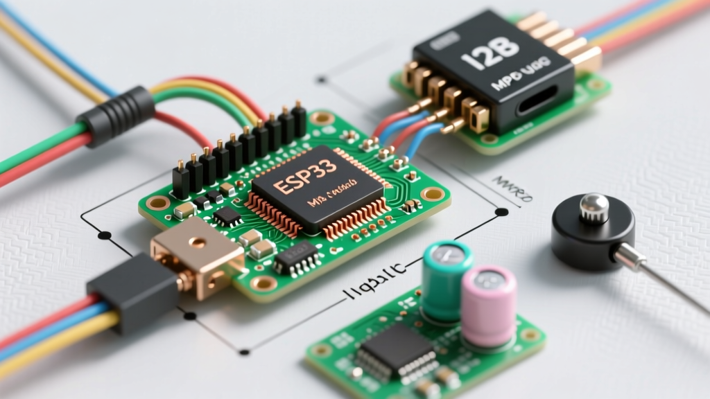
For true high-fidelity audio, sine waves, and multi-voice polyphony, you must abandon the passive buzzer entirely and migrate to an I2S (Inter-IC Sound) architecture. The ESP32 family is the undisputed king of maker audio in 2026, featuring native I2S peripherals and DMA (Direct Memory Access) controllers that stream audio buffers without burdening the main CPU cores.
Hardware Selection: The MAX98357A
The Adafruit MAX98357A I2S Class-D Mono Amplifier is the industry standard for maker upgrades. It takes digital I2S data directly from the ESP32 and outputs up to 3.2W of analog power to a standard 4Ω or 8Ω speaker, completely bypassing the need for external DACs and analog amplifiers. You can reference the official Adafruit MAX98357A wiring guide for detailed breakout pinouts.
Wiring the I2S Migration
When migrating from a 2-wire passive buzzer to an I2S setup, you will need to route three primary data lines alongside power and ground:
- BCLK (Bit Clock): Synchronizes the bit transfer. Connect to ESP32 GPIO 26.
- LRC / WS (Left/Right Clock or Word Select): Dictates the sample rate and channel separation. Connect to ESP32 GPIO 25.
- DIN (Data In): The actual serial audio stream. Connect to ESP32 GPIO 22.
- GAIN: Leave floating for default 15dB gain, or tie to GND for 12dB if your speaker is highly sensitive.
Code Migration: From tone() to I2S Buffers
The most jarring part of the migration is the software paradigm shift. The tone() function is blocking and simplistic. I2S requires buffer management and non-blocking streaming.
The Old Paradigm (Passive Buzzer)
// Blocking, single-thread, square wave only
void playAlert() {
  tone(8, 880, 500); // Pin 8, 880Hz, 500ms
  delay(500); // MCU is frozen here
}
The New Paradigm (I2S Streaming)
When using the ESP32 with the ESP8266Audio library (which fully supports ESP32 I2S architectures), audio generation becomes non-blocking and capable of playing complex WAV files from flash memory or generating synthesized sine waves in real-time.
#include <AudioOutputI2S.h>
#include <AudioGeneratorWAV.h>
#include <AudioFileSourcePROGMEM.h>

AudioGeneratorWAV *wav;
AudioFileSourcePROGMEM *file;
AudioOutputI2S *out;

void setup() {
  // Initialize I2S on the native ESP32 peripheral
  out = new AudioOutputI2S();
  out->SetPinout(26, 25, 22); // BCLK, LRC, DIN

  // Load a high-fidelity WAV file stored in flash
  file = new AudioFileSourcePROGMEM(ui_click_wav, sizeof(ui_click_wav));
  wav = new AudioGeneratorWAV();
  wav->begin(file, out);
}

void loop() {
  // Non-blocking audio processing
  if (wav->isRunning()) {
    wav->loop();
  } else {
    // MCU is free to handle sensors, WiFi, and UI logic
  }
}
For those building custom synthesizers rather than playing back files, the Espressif I2S API documentation provides the low-level register configurations needed to push raw PCM sine-wave buffers directly to the DMA.
Troubleshooting Common Migration Issues
Upgrading audio hardware introduces new failure modes that do not exist with simple passive buzzers. Here is how to diagnose the most common I2S migration headaches:
- Loud "Pop" on Boot: I2S amplifiers like the MAX98357A will aggressively amplify any floating voltages on the DIN or LRC pins while the ESP32 is booting and configuring GPIOs. Solution: Add 10kΩ pull-down resistors on the BCLK, LRC, and DIN lines to keep them at a known LOW state until the I2S peripheral initializes.
- Audio Stuttering / Dropouts: This is rarely an I2S clock issue and almost always a WiFi/Bluetooth interrupt conflict. The ESP32's radio interrupts can starve the I2S DMA buffer. Solution: Pin the I2S audio processing task to Core 1, and restrict all WiFi/Bluetooth stack operations to Core 0 using FreeRTOS task pinning.
- High-Pitched Whine (Ground Loops): If you are powering the ESP32 via USB and the amplifier via a separate bench supply, you will introduce a ground loop. Solution: Ensure a star-ground topology where the GND of the ESP32, the DAC, and the power supply all meet at a single physical point.
Summary
Migrating away from the standard Arduino passive buzzer is a rite of passage for advanced makers. While the KY-006 module is perfect for learning the basics of GPIO toggling and hardware timers, modern projects demand the rich, non-blocking, high-fidelity audio that only I2S DACs and dedicated audio modules can provide. By upgrading to an ESP32 and a MAX98357A amplifier, you eliminate Timer conflicts, protect your MCU from current spikes, and unlock the ability to synthesize professional-grade audio interfaces.