
The Ultimate Arduino Photocell Quick Reference (2026 Edition)
Cadmium Sulfide (CdS) photocells, also known as photoresistors or Light Dependent Resistors (LDRs), remain a staple in DIY electronics due to their simplicity and ultra-low cost. Whether you are building an automated streetlight controller, a solar tracker, or a laser tripwire, integrating an Arduino photocell circuit requires understanding voltage dividers, ADC (Analog-to-Digital Converter) noise management, and environmental edge cases.
This FAQ and quick reference guide cuts through the fluff, providing exact component specifications, circuit mathematics, and production-ready code snippets for your microcontroller projects.
Quick Specification Matrix: Common CdS Photocell Models
Not all photoresistors are created equal. Selecting the right model depends on your target lux range and required response time. Below are the most common 5mm epoxy-coated models available in the 2026 market.
| Model Number | Light Resistance (10 Lux) | Dark Resistance | Response Time (Rise/Decay) | Avg. Cost (Bulk/Unit) |
|---|---|---|---|---|
| GL5528 | 10kΩ - 20kΩ | 1.0 MΩ | 20ms / 30ms | $0.12 / $0.50 |
| GL5516 | 5kΩ - 10kΩ | 0.5 MΩ | 20ms / 30ms | $0.15 / $0.60 |
| GL5537-1 | 20kΩ - 30kΩ | 2.0 MΩ | 30ms / 50ms | $0.18 / $0.75 |
| VT935G (Advanced) | 2kΩ - 5kΩ | 0.2 MΩ | 5ms / 10ms | $0.85 / $1.50 |
Note: Pricing reflects 2026 averages for hobbyist quantities versus AliExpress/Mouser bulk tiers. Pre-wired modules with onboard LM393 comparators typically cost $1.50 to $2.50.
Hardware & Wiring FAQs
Q: Do photocells have polarity? How do I wire one?
A: No, CdS photocells are passive resistors and do not have polarity. You can wire them in either direction. However, because a microcontroller's ADC pin measures voltage, not resistance, you cannot connect a photocell directly to an analog pin and expect meaningful data. You must build a voltage divider.
Expert Wiring Tip: Always place a 0.1µF (100nF) ceramic decoupling capacitor between your analog input pin and GND. This creates a low-pass RC filter that drastically reduces high-frequency ADC jitter caused by nearby digital switching or power supply noise.
Q: What value pull-down resistor should I use?
A: The standard advice is to use a 10kΩ resistor, but this is only optimal if your target lighting condition yields a photocell resistance near 10kΩ. To maximize the ADC resolution (0-1023 on a 10-bit Arduino Uno R3/R4), the fixed resistor ($R_2$) should ideally match the expected resistance of the photocell ($R_1$) in your specific operating environment.
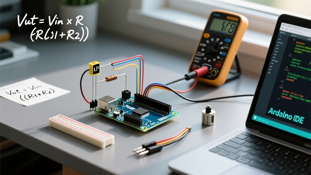
According to SparkFun's Voltage Divider Tutorial, the output voltage ($V_{out}$) is calculated as:
Vout = Vin * (R2 / (R1 + R2))
Example: If you are using a GL5528 in a dimly lit room where the sensor reads roughly 50kΩ, using a 10kΩ pull-down will result in a very low voltage output, wasting most of your ADC's upper range. Swap the fixed resistor to 47kΩ to center the voltage near 2.5V (yielding an analogRead() value around 512).
Q: Pull-down vs. Pull-up configuration: Which is better?
- Pull-Down (Fixed resistor to GND): As light increases, photocell resistance drops, and the analog reading increases (towards 1023). This is the most intuitive setup for beginners.
- Pull-Up (Fixed resistor to 5V): As light increases, the analog reading decreases (towards 0). Use this if you want to utilize the Arduino's internal pull-up resistors, though internal pull-ups are typically 20kΩ-50kΩ, which limits your tuning precision.
Code, Calibration & Data Processing
Q: How do I map raw analogRead() values to usable Lux or percentages?
A: Raw ADC values are highly dependent on your specific voltage divider and ambient light. Instead of hardcoding magic numbers, implement a dynamic calibration routine during the first 3 seconds of the setup() loop. For deeper mathematical conversions from resistance to Lux, refer to the logarithmic curves provided in Adafruit's Photocell Guide.
Here is a robust calibration and mapping snippet:
const int photocellPin = A0;
int minVal = 1023;
int maxVal = 0;

void setup() {
  Serial.begin(115200);
  // 3-second calibration window
  unsigned long startTime = millis();
  while(millis() - startTime < 3000) {
    int currentRead = analogRead(photocellPin);
    if(currentRead < minVal) minVal = currentRead;
    if(currentRead > maxVal) maxVal = currentRead;
    delay(10);
  }
  Serial.print("Calibrated Min: "); Serial.println(minVal);
  Serial.print("Calibrated Max: "); Serial.println(maxVal);
}

void loop() {
  int raw = analogRead(photocellPin);
  // Map to a 0-100 percentage scale, constrain to prevent overflow
  int lightPercent = map(raw, minVal, maxVal, 0, 100);
  lightPercent = constrain(lightPercent, 0, 100);
  Serial.println(lightPercent);
  delay(100);
}
Q: Why are my readings jittery, and how do I smooth them without using delay()?
A: Jitter is inherent to 10-bit SAR (Successive Approximation Register) ADCs, especially on older boards like the Uno R3. Using delay() to average readings blocks your main loop. Instead, use an Exponential Moving Average (EMA) filter. It requires minimal memory and executes in microseconds.
float smoothedVal = 0;
const float alpha = 0.1; // Smoothing factor (0.0 to 1.0)

void loop() {
  int raw = analogRead(A0);
  smoothedVal = (alpha * raw) + ((1 - alpha) * smoothedVal);
  // Use smoothedVal for your logic
}
Advanced Troubleshooting & Edge Cases
Q: Why does my sensor lag when the lights turn off?
A: CdS photocells suffer from asymmetric response latency. While the resistance drops almost instantly when exposed to light (rise time ~20ms), the chemical recombination of electrons and holes in the cadmium sulfide lattice takes significantly longer when light is removed (decay time ~30ms to 50ms+). If your project requires symmetrical, high-speed optical detection (e.g., reading encoder wheels or fast laser tripwires), abandon CdS cells and use a BPW34 Photodiode or a TEMT6000 Ambient Light Sensor, which operate in the microsecond range.
Q: Does temperature affect Arduino photocell accuracy?
A: Yes. CdS sensors have a noticeable temperature coefficient. In extreme cold (below 0°C), the dark resistance can increase by up to 50%, while high heat (above 60°C) can cause the sensor to become overly sensitive and drift. If your project is deployed outdoors in a 2026 smart agriculture setup, you must pair the LDR with a thermistor (like the NTC 10k B3950) and apply a software temperature-compensation matrix to your lux calculations.
Q: Can I use a 3.3V microcontroller (ESP32, Nano 33 IoT)?
A: Absolutely, but you must respect the ADC reference voltage. On a 5V Arduino, analogRead() maps 0-5V to 0-1023. On a 3.3V ESP32, the ADC maps 0-3.3V to 0-4095 (12-bit).
Warning: The ESP32's ADC is notoriously non-linear at the extreme high and low ends of its voltage range (near 0V and above 3.0V). When designing your voltage divider for an ESP32, aim to keep your expected $V_{out}$ strictly between 0.5V and 2.8V to ensure linear, accurate data. Furthermore, the official Arduino analogRead() documentation notes that higher resolution boards may require discarding the lowest 2 bits of data via bitwise shifting if you want to maintain compatibility with legacy 10-bit logic.
Q: My photocell reads 1023 constantly, even in the dark. What's wrong?
A: You have a floating pin. This usually happens if the ground wire to your pull-down resistor is disconnected, or if you wired the photocell directly between 5V and the Analog pin without a resistor to GND. The ADC pin acts as an antenna, picking up electromagnetic interference (EMI) and maxing out the register. Double-check your breadboard ground rails and ensure your multimeter reads a stable voltage at the junction of the photocell and the fixed resistor.