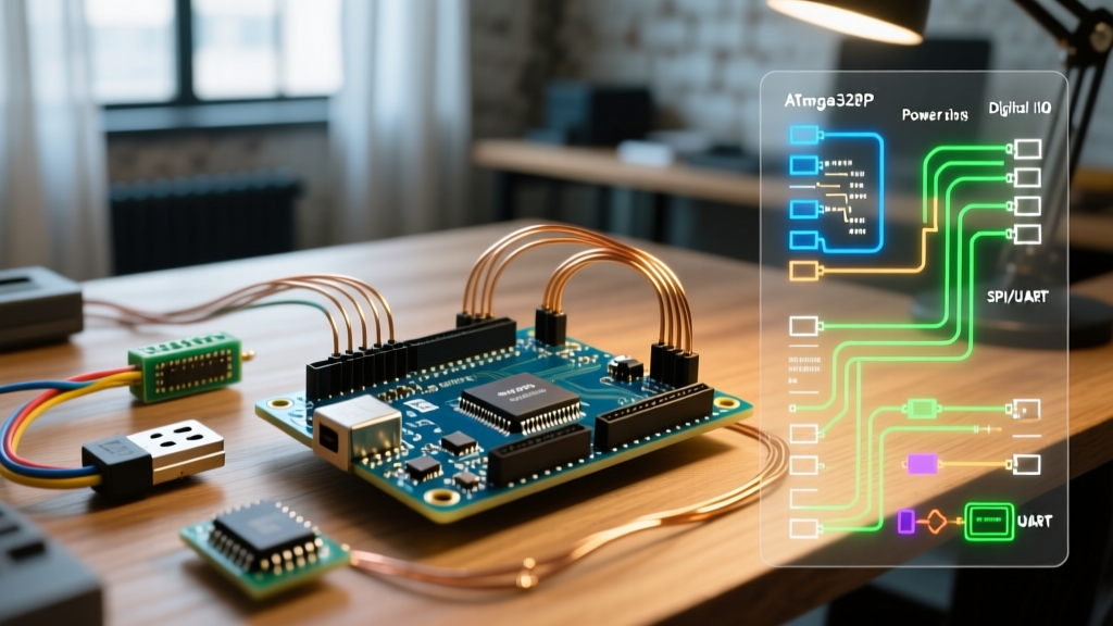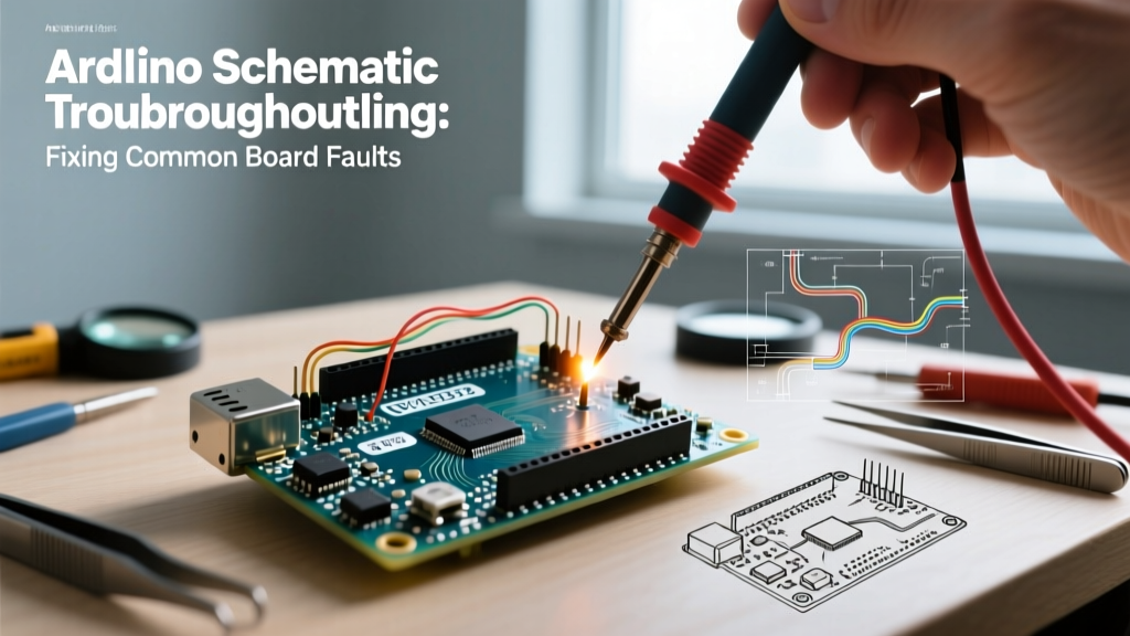

The Diagnostic Power of the Arduino Schematic
When an Arduino board fails to upload, overheats, or enters a perpetual reset loop, most makers immediately toss it into the e-waste bin and order a replacement. However, a genuine Arduino Uno R3 costs around $27.50, and even high-quality clones sit in the $9 to $14 range. Before discarding a board, understanding how to read and navigate an Arduino schematic transforms you from a passive consumer into an active hardware debugger. The schematic is your ultimate diagnostic map, revealing the exact path of power rails, data lines, and pull-up networks that govern the microcontroller's behavior.
In this troubleshooting guide, we will dissect the official Arduino Uno Rev3 documentation and schematic to isolate and repair three of the most common hardware-level failures: 5V rail collapse, USB enumeration errors, and phantom resets. Grab your multimeter, fire up your soldering station, and let us trace the copper.
⚠️ Safety & Preparation Warning: Always disconnect the board from USB and external power supplies before performing continuity or resistance checks. When measuring live voltage, use insulated probes and keep your fingers behind the probe guards to prevent shorting adjacent SMD pads.
Fault 1: Voltage Regulator Overheating (5V Rail Collapse)
The most frequent catastrophic failure on an Arduino Uno occurs when a user back-feeds voltage into the 5V pin or exceeds the input limits on the barrel jack. The schematic reveals that the 5V rail is governed by IC1, an NCP1117ST50T3G linear voltage regulator. According to the ON Semiconductor NCP1117 datasheet, this SOT-223 packaged component has a thermal shutdown threshold of approximately 150°C.
Step-by-Step Diagnostic Flow
- Check the Input Diode (D1): The barrel jack is protected by an M7 surface-mount diode. Set your multimeter to Diode Test mode. Place the red probe on the anode (input side) and black on the cathode (regulator side). A healthy M7 diode will show a forward voltage drop of roughly 0.5V to 0.7V. If it reads 0.00V (short) or OL (open), replace the diode.
- Verify the Polyfuse (F1): If the board is completely dead via USB, check the resettable PTC polyfuse (F1) located near the USB port. It is rated for 500mA. Measure resistance across it; it should read near 0Ω. If it reads high resistance, it has tripped or failed. Let it cool for 10 minutes and retest.
- Isolate the Regulator (IC1): If the board gets scalding hot near the barrel jack, IC1 is likely shorted internally. Measure the resistance between the 5V output pin of IC1 and GND. A reading below 50Ω indicates a dead regulator or a shorted downstream component (like the ATmega328P or the 100nF decoupling capacitors).
The Repair Procedure
Replacing the NCP1117ST50T3G costs less than $0.50 for the component. Apply flux to the SOT-223 pads, use a hot air rework station set to 350°C with a 10mm nozzle, and gently lift the faulty IC with tweezers. Clean the pads with 2.0mm desoldering wick, tin them with fresh 63/37 leaded solder, and align the new regulator. Heat the large thermal tab first to anchor the part, then flow solder onto the two smaller pins.
Fault 2: USB Enumeration Failure (ATmega16U2 Isolation)
When your PC displays "USB Device Not Recognized," the issue rarely lies with the main ATmega328P microcontroller (U1). The schematic shows that USB-to-Serial conversion is handled by a secondary chip: the ATmega16U2-MU (U2). If U2 fails to enumerate, your operating system will never assign a COM port, rendering the IDE useless.
Tracing the USB Data Lines
The USB connector routes D- and D+ through an ESD protection array (PR1, typically a USB6B1 or similar diode array) before reaching pins 29 and 30 of U2. If a static shock has destroyed the data lines, PR1 is the first line of defense and usually takes the hit.
- Test PR1: Use the diode test function on your multimeter. Measure from the USB D+ pad to GND, and D- to GND. Both should show a diode drop (approx. 0.6V). If either reads as a dead short (0.00V), the ESD array is fried and is pulling the data lines low, preventing enumeration.
- Check the Crystal Oscillator (Y2): U2 requires a precise 16MHz clock signal to handle USB Full-Speed (12 Mbps) communication. If the 16MHz crystal (Y2) or its accompanying 22pF load capacitors (C8 and C9) are cracked or missing, U2 will not start. An oscilloscope probe on pin 7 of U2 should show a clean 16MHz sine wave. If you lack a scope, visually inspect Y2 for micro-fractures and reflow its pads with a soldering iron at 320°C.
Fault 3: Phantom Resets and Bootloader Loops
A board that constantly resets, flashes the pin 13 LED erratically, or fails to hold a user sketch is often suffering from a compromised reset circuit. The Arduino schematic utilizes an auto-reset feature that allows the IDE to trigger a bootloader without a physical button press. This is achieved via the DTR (Data Terminal Ready) signal from the 16U2.
Analyzing the Reset Network
The RESET line is pulled high to 5V via a 10kΩ resistor (R3) and coupled to the DTR line via a 100nF capacitor (C5). When the IDE opens the serial port, DTR drops low, pulling the RESET pin low through C5 just long enough to trigger the bootloader.
| State | Expected Voltage at RESET | Multimeter Reading | Probable Fault if Deviating |
|---|---|---|---|
| Idle (No Upload) | 5.0V (Stable High) | 4.8V - 5.1V | Leaky C5 capacitor or damaged R3 pull-up |
| Active Upload (IDE Connecting) | Brief drop to ~0.2V | Transient spike | Missing C5 prevents auto-reset; requires manual button press |
| Stuck in Reset | 0.0V (Constant Low) | 0.0V - 0.1V | Shorted C5, stuck tactile switch (S1), or dead ATmega328P |
The Fix: If the board is stuck in reset, measure the resistance between the RESET header pin and GND. It should read >1MΩ. If it reads near 0Ω, the 100nF capacitor (C5) has likely failed short. Desolder C5 using a fine-tip iron and replace it with a standard 0603 or 0805 100nF X7R ceramic capacitor. As noted in SparkFun's multimeter guide, always ensure your meter is set to the correct resistance range to avoid false continuity readings caused by parallel IC impedance.
Component-Level Repair vs. Board Replacement Matrix
Not every fault justifies a 30-minute micro-soldering session. Use the matrix below to decide whether to repair the board based on the schematic diagnosis or simply replace it.
| Fault Scenario | Component Cost | Repair Time | Skill Required | Verdict |
|---|---|---|---|---|
| Blown M7 Input Diode | $0.10 | 5 Minutes | Beginner (SMD) | Repair - Excellent practice for SMD soldering. |
| Dead NCP1117 Regulator | $0.45 | 15 Minutes | Intermediate (Hot Air) | Repair on Genuine boards; replace clones. |
| Shorted ESD Array (PR1) | $0.30 | 10 Minutes | Intermediate | Repair - Critical for protecting your PC's USB port. |
| Cracked ATmega328P (U1) | $4.50 (Pre-flashed) | 45 Minutes | Advanced (TQFP-32) | Replace Board - TQFP drag soldering is highly prone to bridging. |
| Delaminated USB-B Connector | $0.80 | 20 Minutes | Intermediate | Repair - Requires heavy thermal mass for the ground shield tabs. |
Essential Tools for Schematic-Level Debugging
To effectively troubleshoot using an Arduino schematic, you need more than just a basic soldering iron. Equip your bench with the following:
- True RMS Digital Multimeter: Essential for accurate diode testing and millivolt measurements across sense resistors. (Budget: $40 - $80)
- Hot Air Rework Station: Required for removing multi-pad SMD ICs like the NCP1117 or ATmega16U2 without tearing the PCB pads. Look for models with digital temperature and airflow control. (Budget: $65 - $150)
- ChipQuik SMD291AX Flux: Tacky flux is non-negotiable for SMD rework. It prevents solder bridging and ensures proper wetting on oxidized pads. (Budget: $12)
- Fine Desoldering Wick: 1.0mm and 2.0mm copper braid for cleaning pads before placing new components. (Budget: $8)
Frequently Asked Questions (FAQ)
Where can I find the official schematics for newer boards like the Uno R4?
Arduino has shifted toward providing comprehensive hardware documentation, including interactive schematics and Gerber files, via their official documentation portal. For the Uno R4 Minima and WiFi, the schematics are available in the respective hardware sections of the Arduino Docs site. Note that the R4 series uses a Renesas RA4M1 ARM Cortex-M4, meaning the power architecture and USB routing differ significantly from the legacy R3 ATmega-based designs.
Can I bypass a dead voltage regulator and power the board directly?
Yes. The schematic shows that the 5V pin on the header is directly connected to the output of the NCP1117 and the 5V net of the ATmega328P. If IC1 is dead but the rest of the board is intact, you can physically remove IC1 to prevent it from dragging the rail down, and then feed a clean, regulated 5.0V (±0.2V) directly into the 5V header pin. Never exceed 5.5V on this pin, as you will instantly destroy the main microcontroller.
Why does my multimeter show a short to ground on the 5V pin?
When the board is unpowered, the multimeter's internal battery sends a small current through the 5V rail to measure resistance. Because the 5V rail has multiple decoupling capacitors (100nF and 10µF) connected to ground, the meter will initially read a low resistance or beep a continuity alarm until the capacitors charge. Wait 3 to 5 seconds; if the resistance climbs to the kilo-ohm range, there is no short. If it stays below 10Ω, you have a failed capacitor or a shorted IC.