
Understanding Arduino Buttons Compatibility
When integrating physical inputs into a microcontroller project, selecting the right switch is only half the battle. True compatibility involves matching the mechanical switch characteristics to the microcontroller's logic levels, internal pin configurations, and signal processing capabilities. While a button is fundamentally just a conductive bridge, improper pairing with an Arduino or ESP32 can result in floating pins, boot failures, and erratic state readings.
This guide breaks down the electrical and mechanical compatibility of various switch types with modern 8-bit and 32-bit microcontrollers, providing exact wiring topologies and edge-case troubleshooting for 2026 maker projects.
Switch Types and Microcontroller Logic Matrix
Different applications demand different actuation forces, travel distances, and electrical ratings. Below is a compatibility matrix comparing the most common switch types used in Arduino ecosystems.
| Switch Type | Standard Model | Actuation Force | Avg Bounce Time | Est. Cost (2026) | Best Application |
|---|---|---|---|---|---|
| Tactile (SPST) | Omron B3F-1000 (6x6mm) | 150g - 250g | 5ms - 20ms | $0.10 - $0.25 | General UI, reset, mode selection |
| Mechanical (Keyboard) | Cherry MX1A-11NW (Red) | 45cN (Linear) | 10ms - 30ms | $0.40 - $0.80 | Custom macros, high-end HID devices |
| Capacitive Touch | TTP223-BA6 Module | N/A (Touch) | 0ms (IC handled) | $1.20 - $1.80 | Sealed enclosures, waterproof UI |
| Reed Switch (Magnetic) | Meder SIL Series | Magnetic Field | 1ms - 5ms | $0.80 - $1.50 | Door sensors, limit switches |
Pull-Up vs. Pull-Down: Wiring Logic Correctly
A common beginner mistake is wiring a button directly between a digital pin and ground without a reference voltage, resulting in a 'floating' pin that reads random electromagnetic noise. To fix this, a pull-up or pull-down resistor is required.
Leveraging Internal Pull-Up Resistors
Most modern microcontrollers, including the ATmega328P (Arduino Uno) and ESP32, feature internal pull-up resistors. By configuring the pin via pinMode(pin, INPUT_PULLUP), you connect an internal resistor (typically 20kΩ to 50kΩ) to the logic HIGH voltage. According to the Arduino Digital Pins Documentation, this eliminates the need for external resistors in low-noise environments.
- Wiring: Pin A to Button Leg 1; Button Leg 2 to GND.
- Logic: Pin reads HIGH when open, LOW when pressed.
- Limitation: Internal pull-ups are weak. If your wire run exceeds 30cm, the high impedance can act as an antenna for 50/60Hz mains hum.
When to Use External Resistors
For industrial environments or long cable runs, an external 10kΩ pull-up resistor tied to the 3.3V or 5V logic rail is mandatory. As detailed in SparkFun's Pull-Up Resistor Guide, a 10kΩ value provides a strong enough pull to overcome parasitic capacitance while keeping current draw low (0.5mA at 5V) when the button is pressed.
Edge Case: ESP32 Strapping Pin Conflicts
When using Arduino buttons with 3.3V boards like the ESP32 or ESP32-S3, you must account for boot strapping pins. The ESP32 uses specific GPIOs (notably GPIO 0, 2, and 12) to determine boot modes during power-on.
Critical Warning: If you wire a button with an external pull-up resistor to GPIO 0, the ESP32 will read HIGH on boot and fail to enter the UART download mode, causing sketch uploads to fail. Always use GPIOs like 4, 5, 16, or 17 for button inputs on the original ESP32, or rely strictly on internal pull-downs if the specific pin supports it.
The Debounce Dilemma: Hardware vs. Software
Mechanical contacts do not close cleanly; they physically bounce, creating multiple rapid HIGH/LOW transitions. As explained in All About Circuits' technical guide on switch bounce, a single press can register as a dozen inputs to a microcontroller running at 16MHz or 240MHz.
Software Debouncing (The Standard Approach)
For 90% of projects, software debouncing is sufficient. The Bounce2 library is the industry standard for Arduino. Setting an interval of 20ms to 50ms filters out the mechanical noise without introducing noticeable input lag.
#include <Bounce2.h>
Bounce debouncer = Bounce();
void setup() {
  pinMode(2, INPUT_PULLUP);
  debouncer.attach(2);
  debouncer.interval(25); // 25ms debounce time
}
Hardware Debouncing (For Interrupts and Fast UI)
If your button triggers a hardware interrupt (ISR), software debouncing libraries will fail or crash the MCU. You must use an RC (Resistor-Capacitor) low-pass filter.
- Place a 10kΩ resistor in series with the switch output.
- Place a 100nF (0.1µF) ceramic capacitor between the MCU pin and GND.
- This creates a time constant ($\tau = R \times C$) of 1ms, physically smoothing the voltage spike before the microcontroller's Schmitt trigger reads it.
Step-by-Step: Wiring a Standard Tactile Button
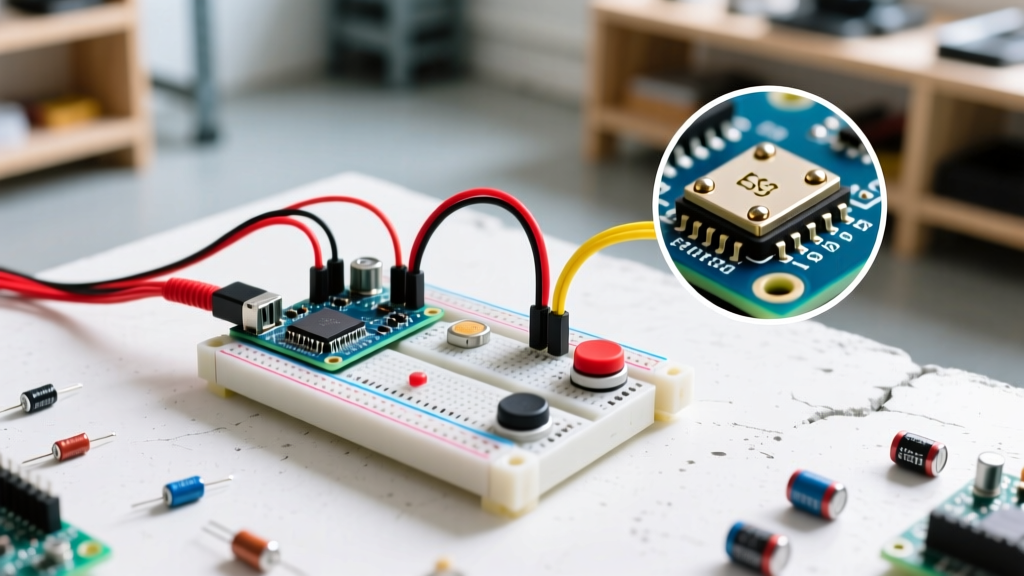
Follow this exact topology for a standard 6x6mm Omron B3F tactile switch on a breadboard using an Arduino Uno R4.
- Orientation: Straddle the breadboard center ditch. Ensure the pins are on opposite sides (pins 1 & 2 on row 10, pins 3 & 4 on row 10). If rotated 90 degrees, the button will be permanently closed.
- Ground Connection: Insert a jumper wire from row 10, pin 1 to the breadboard GND rail.
- Signal Connection: Insert a jumper wire from row 10, pin 2 to Arduino Digital Pin 3.
- Code Configuration: Initialize Pin 3 as
INPUT_PULLUPin your setup loop. - Validation: Open the Serial Monitor at 115200 baud. Press the button; the state should cleanly transition from 1 (HIGH) to 0 (LOW).
Troubleshooting Common Button Failures
- Ghost Presses / Floating States: You forgot the pull-up resistor. Add
INPUT_PULLUPto your code or wire a physical 10kΩ resistor to VCC. - Multiple Inputs per Press: Mechanical bounce. Implement the Bounce2 library or add a 100nF hardware capacitor.
- Pin Reads LOW Constantly: The tactile switch is rotated 90 degrees on the breadboard, shorting the internal bridge continuously. Rotate it 90 degrees.
- ESP32 Upload Failures: Your button is wired to GPIO 0 with a pull-up resistor, preventing the bootloader from triggering. Move the button to a safe GPIO like 4 or 5.
- Oxidation in High-Humidity: Standard copper-alloy tactile switches oxidize, increasing contact resistance. For outdoor or high-humidity projects, specify switches with silver-plated or gold-flashed contacts (e.g., C&K PTS645 series).