
Configuring the correct Arduino resistor network is the dividing line between a reliable embedded project and a fried microcontroller. Whether you are working with the classic ATmega328P on an Uno R3 or the 3.3V logic of an ESP32-S3, misjudging resistance values can lead to excessive current draw, I2C bus collisions, or inaccurate ADC readings. In 2026, with maker components becoming more miniaturized and logic voltages dropping to 3.3V and 1.8V, precision in resistor selection is no longer optional.
This configuration guide moves beyond basic Ohm's law. We will cover exact value calculations, advanced edge cases like ADC source impedance, and hardware selection for your workbench.
Core Arduino Resistor Configurations
1. LED Current Limiting (GPIO Pins)
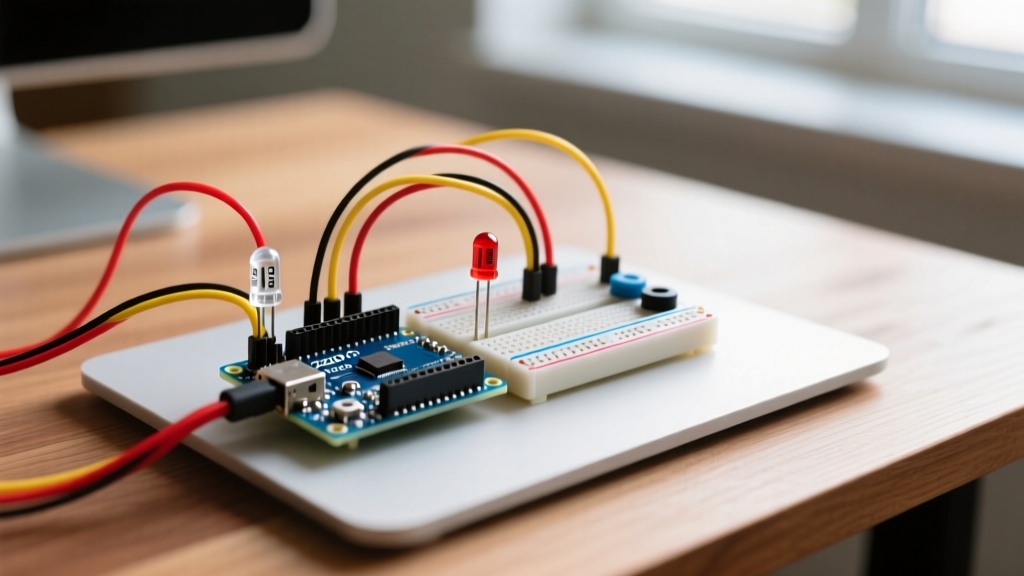
The most common use case for an Arduino resistor is current limiting for indicator LEDs. A standard ATmega328P GPIO pin can source an absolute maximum of 40mA, but the recommended continuous current is 20mA. Pushing pins to their absolute limit degrades the silicon over time and causes voltage droop on the Vcc rail.
To calculate the exact resistor value, use the standard diode equation:
R = (Vcc - Vf) / If
Where Vcc is logic voltage (5V or 3.3V), Vf is the LED forward voltage, and If is the target current (usually 0.015A for modern high-efficiency LEDs).
- Red/Green/Yellow LEDs (Vf ≈ 2.0V - 2.2V): On a 5V Arduino, targeting 15mA requires R = (5 - 2.0) / 0.015 = 200Ω. The nearest standard E24 value is 200Ω or 220Ω.
- Blue/White/UV LEDs (Vf ≈ 3.2V): On a 5V system, R = (5 - 3.2) / 0.015 = 120Ω. Use a 120Ω or 150Ω resistor.
- 3.3V Logic (ESP32/RP2040): You cannot safely drive a 3.2V Blue LED directly from a 3.3V pin with a standard resistor, as the voltage headroom (0.1V) is too small to regulate current. Use a MOSFET driver or a dedicated LED driver IC instead.
2. I2C Pull-Up Resistor Networks
The I2C protocol uses open-drain outputs, meaning the MCU can pull the SDA and SCL lines LOW, but it cannot drive them HIGH. External pull-up resistors are mandatory. While the ATmega328P has internal pull-ups (typically 20kΩ to 50kΩ), they are far too weak for reliable I2C communication, especially at Fast Mode (400kHz) speeds.
According to the official NXP I2C-bus specification, the pull-up resistor value is dictated by the bus capacitance (Cb) and the desired rise time (tr). For most standard Arduino breadboard setups with a few sensors:
- Standard Mode (100kHz): Use 4.7kΩ resistors.
- Fast Mode (400kHz): Use 2.2kΩ or 1kΩ resistors to overcome parasitic capacitance and ensure fast rise times.
Pro-Tip: If you are daisy-chaining multiple I2C modules (like an OLED display, BME280, and MPU6050), the cumulative bus capacitance increases. You must lower the resistance value (e.g., down to 2.2kΩ) to maintain signal integrity. For a deep dive into the physics of these configurations, SparkFun's pull-up resistor tutorial provides excellent oscilloscope captures showing signal degradation.
3. Switch and Button Configurations
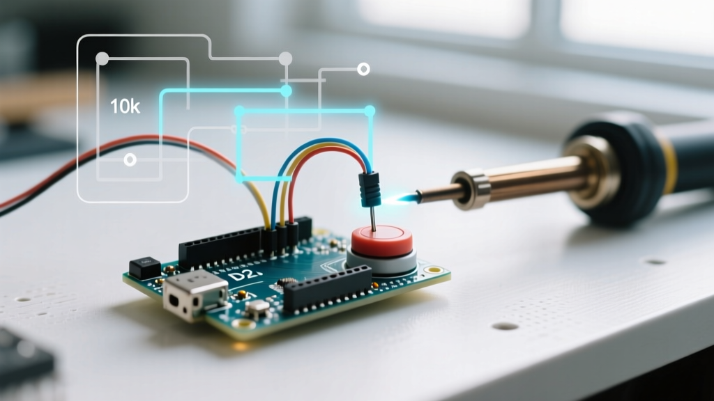
Mechanical switches require a defined logic state when open. While you can use external 10kΩ pull-down resistors, modern Arduino development heavily favors internal pull-ups. By configuring the pin mode to INPUT_PULLUP in your sketch, you activate the silicon's internal ~30kΩ resistor, wiring the button directly to ground. This eliminates the need for external resistors for simple inputs. However, for electrically noisy environments (like automotive or motor-control enclosures), an external 1kΩ to 4.7kΩ pull-up provides a much stiffer, noise-immune logic HIGH.
Configuration Matrix: Common Arduino Resistor Values
| Application | Target Vcc | Recommended Value | Tolerance | Power Rating |
|---|---|---|---|---|
| Standard Red LED Limiting | 5.0V | 220Ω | 5% (Carbon) | 1/4W |
| I2C Bus Pull-Up (100kHz) | 5.0V / 3.3V | 4.7kΩ | 1% (Metal Film) | 1/4W |
| I2C Bus Pull-Up (400kHz) | 3.3V | 2.2kΩ | 1% (Metal Film) | 1/4W |
| External Button Pull-Up | 5.0V | 10kΩ | 5% (Carbon) | 1/4W |
| ADC Voltage Divider (12V to 5V) | 12V Input | 10kΩ / 6.8kΩ | 1% (Metal Film) | 1/4W |
Advanced Edge Case: ADC Source Impedance
A frequent failure mode in Arduino sensor configuration is using high-value resistors in a voltage divider feeding an analog pin (ADC). The ATmega328P datasheet explicitly states that the analog source impedance should be 10kΩ or less.
Inside the MCU, the ADC uses a sample-and-hold (S/H) capacitor (approx. 14pF). When the multiplexer switches to your pin, this capacitor must charge to the input voltage within a fraction of the ADC clock cycle. If your voltage divider uses 100kΩ and 100kΩ resistors to save power, the RC time constant is too slow. The S/H capacitor won't fully charge, resulting in erratic, lower-than-expected analogRead() values. Always configure your ADC dividers with a total equivalent resistance under 10kΩ, or buffer the signal with an op-amp.
Hardware Selection: 2026 Workbench Kits
For general prototyping, the industry has largely moved away from 5% tolerance carbon composition resistors in favor of 1% metal film resistors. Metal film offers lower thermal noise and better long-term stability, which is critical for I2C and ADC configurations.
In 2026, a comprehensive 600-value 1/4W metal film kit (such as those from RexQualis or Elegoo) costs between $10.99 and $14.99. When purchasing, verify that the kit includes the E24 series values (like 220, 470, 2.2k, 4.7k) rather than just E12, as E24 provides the precise values needed for accurate voltage dividers.
Step-by-Step Wiring Verification Protocol
Before applying power to a newly configured Arduino resistor network, follow this verification protocol to prevent catastrophic shorts:
- Visual Inspection: Verify resistor color bands or SMD markings. Confirm a 4.7kΩ (Yellow-Violet-Red) hasn't been accidentally swapped with a 470Ω (Yellow-Violet-Brown).
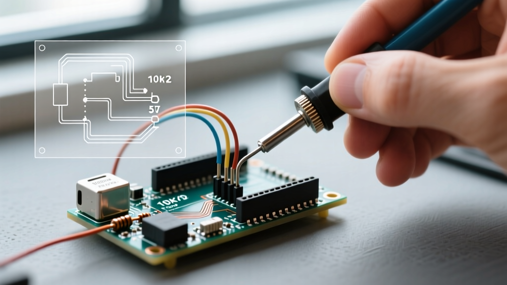
- Continuity Check: Set your multimeter to continuity mode. Probe the Vcc and GND rails of your breadboard. Ensure no solder bridges or bent jumper wires are creating a dead short.
- Resistance Measurement: Measure the resistance of the configured network in-circuit (with power OFF). Note that parallel paths (like an internal MCU protection diode) may slightly skew the reading, but it should be within 10% of your target.
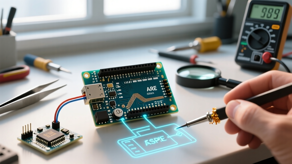
- Voltage Verification: Power the Arduino. Use the multimeter's DC voltage mode to probe the node between the resistor and the load (e.g., the anode of the LED or the SDA line). Ensure it matches your expected logic HIGH voltage.
Frequently Asked Questions
Can I use a single resistor for multiple parallel LEDs?
No. Due to manufacturing variances, the forward voltage (Vf) of individual LEDs differs slightly. If you wire them in parallel with one shared resistor, the LED with the lowest Vf will hog the majority of the current, leading to thermal runaway and premature failure. Always configure a dedicated resistor for each LED.
Do I need resistors for SPI or UART pins?
Generally, no. SPI and UART use push-pull outputs, meaning the MCU actively drives the line both HIGH and LOW. Series resistors (usually 22Ω to 33Ω) are sometimes added to high-speed SPI lines to dampen signal reflections and reduce EMI, but they are not required for basic low-speed Arduino configurations.
What happens if I forget the pull-up resistor on an I2C bus?
The SDA and SCL lines will float. The Wire library will attempt to communicate, but the lines will never return to a logic HIGH state. Your Arduino sketch will typically hang or freeze at the Wire.endTransmission() command, requiring a hard reset.