
The Definitive Arduino Mini Pro Pinout Breakdown
Despite the proliferation of modern ESP32 and RP2040 boards, the Arduino Pro Mini remains a staple in the maker community for low-power, battery-operated embedded projects. Its minimal footprint, lack of onboard USB-to-Serial overhead, and raw ATmega328P performance make it irreplaceable for remote sensor nodes. However, because it strips away the hand-holding of the Arduino Uno, understanding the exact Arduino Mini Pro pinout is critical for avoiding hardware damage and software bugs.
Below is the comprehensive pinout reference for both the 5V/16MHz (SparkFun DEV-11114) and 3.3V/8MHz (DEV-11113) variants, reflecting community-verified schematics as of 2026.
| Pin Label | ATmega328P Port | Primary Function | Community Notes & Edge Cases |
|---|---|---|---|
| D0 (RX) / D1 (TX) | PD0 / PD1 | Hardware Serial (UART) | Shared with the FTDI header. Do not use for external I2C or SPI. |
| D2 - D7 | PD2 - PD7 | Digital I/O, Interrupts | D2 and D3 support hardware external interrupts (INT0, INT1). |
| D8 - D13 | PB0 - PB5 | Digital I/O, SPI | D11 (MOSI), D12 (MISO), D13 (SCK). D13 is also the onboard LED. |
| A0 - A5 | PC0 - PC5 | Analog In / Digital I/O | A4 (SDA) and A5 (SCL) are used for I2C communication. |
| A6 / A7 | ADC6 / ADC7 | Analog Input ONLY | Warning: Cannot be used as digital I/O. No internal pull-ups. |
| RAW | N/A | Unregulated Power In | Accepts 5V-12V (5V board) or 3.5V-12V (3.3V board). Feeds the LDO. |
| VCC | VCC | Regulated Power Out/In | Outputs 5V or 3.3V. Can be used as direct power input to bypass LDO. |
The A6 and A7 Analog-Only Trap
One of the most frequent issues documented in community forums is the attempted use of A6 and A7 as digital pins. Unlike A0 through A5, which map to PORTC and support both digitalWrite() and analogRead(), A6 and A7 are dedicated ADC (Analog-to-Digital Converter) pins on the ATmega328P QFP package. They lack digital data buffers. Attempting to use them with pinMode(A6, OUTPUT) will fail silently, leading to hours of frustrating debugging. Always reserve A6 and A7 strictly for analog sensor readings, such as battery voltage monitoring via a voltage divider.
Community-Tested Hardware Variants & Clones
When sourcing Pro Mini boards in 2026, makers generally choose between the original SparkFun designs and generic overseas clones. Understanding the hardware differences is vital for power-sensitive applications.
- SparkFun Original (DEV-11113 / DEV-11114): Priced around $12.50. Features the high-quality MIC5205 Low-Dropout (LDO) regulator with a low quiescent current of ~1.2mA. Excellent for reliable deployments.
- Generic HW-111 Clones: Priced between $1.50 and $2.80 on bulk marketplaces. Often use cheaper, unmarked LDOs with quiescent currents exceeding 5mA. The onboard 32.768 kHz crystal for the Real-Time Clock (RTC) is frequently missing or populated with a non-functional dummy component.
- Baite / Funduino Variants: These often feature a slightly wider PCB layout to accommodate larger solder pads, making them easier to hand-solder for beginners, but they sacrifice the compact footprint that makes the Pro Mini ideal for custom enclosures.
Top Community Resources & Schematics
To truly master this board, you need to look beyond the basic IDE examples. Here is a curated roundup of the most authoritative, community-vetted resources for the Arduino Pro Mini.
- Official Arduino Board Documentation: The foundational reference for the board's origins and basic electrical characteristics. The Arduino Pro Mini official page provides the baseline schematics and ATmega328P datasheet links necessary for understanding the underlying silicon.
- SparkFun Hookup Guide & Eagle Files: For those designing custom carrier boards or needing to trace the exact PCB routing, the SparkFun Pro Mini Hookup Guide remains the gold standard. It includes downloadable Eagle/Altium design files, allowing you to import the exact footprint into your own KiCad or Altium projects.
- Nick Gammon’s Power Saving Deep Dive: The undisputed bible for low-power ATmega328P programming. Gammon's power saving guide details how to disable the ADC, Brown-Out Detection (BOD), and Watchdog Timer to push the Pro Mini into micro-amp sleep states. This is mandatory reading for anyone building solar-powered or coin-cell-driven sensor nodes.
Real-World Upload Troubleshooting: The FTDI DTR Edge Case
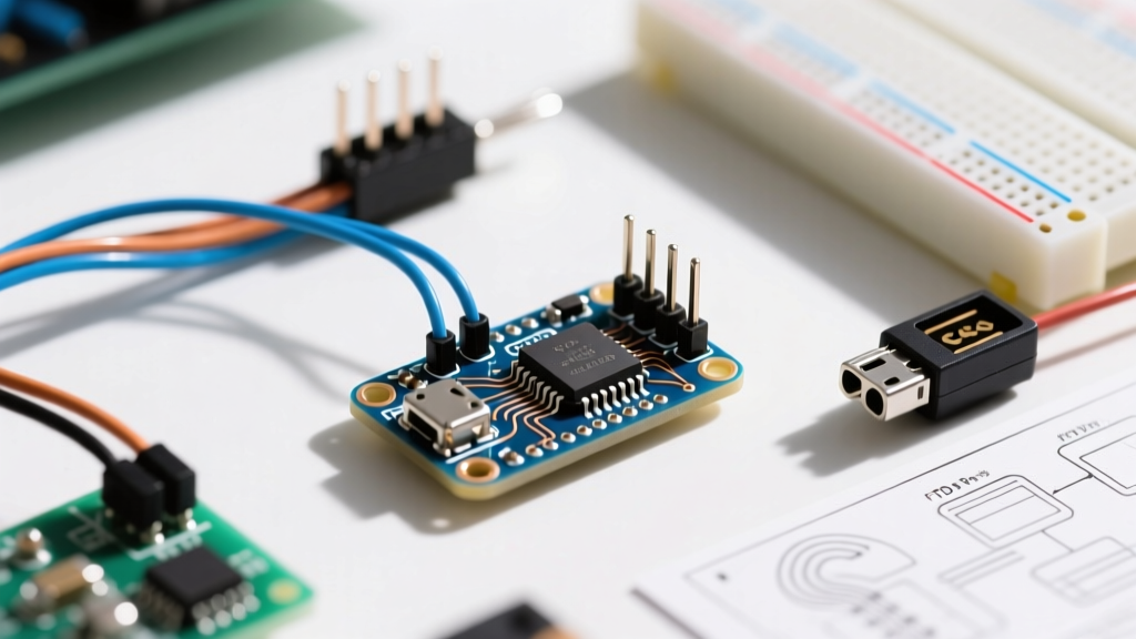
Because the Pro Mini lacks an onboard USB-to-Serial chip, you must use an external FTDI Basic programmer or a generic USB-TTL adapter (like the CP2102 or CH340). A common failure mode in community builds is the 'Out of Sync' or 'Programmer is not responding' error during sketch uploads.
Community Pro-Tip: The auto-reset circuit relies on a 0.1µF capacitor placed between the DTR (Data Terminal Ready) line of the FTDI adapter and the RESET pin of the ATmega328P. If your generic USB-TTL adapter only breaks out the RTS (Request to Send) pin instead of DTR, the board will not automatically reset into the bootloader. You must either wire RTS through a 0.1µF capacitor to the GRN/DTR pin, or perform the 'Manual Reset Timing Trick': press and hold the physical reset button on the Pro Mini, click 'Upload' in the IDE, and release the button the exact millisecond the IDE console says 'Done compiling'.
Furthermore, ensure your FTDI adapter's voltage switch matches the board. Feeding 5V logic from an FTDI adapter into the RX pin of a 3.3V/8MHz Pro Mini can slowly degrade the ATmega328P's input protection diodes, leading to phantom current leaks and eventual chip failure.
Advanced Power Optimization: Stripping the Board
Out of the box, a 3.3V Arduino Pro Mini drawing sleep current via the LowPower.powerDown() library will still consume roughly 4.5mA to 5.5mA. For a project running on a 2000mAh 18650 lithium cell, this limits battery life to a few weeks. To achieve the ATmega328P's theoretical sleep current of ~10µA, the community recommends physical board modifications.
Step-by-Step Board Stripping Guide
- Remove the Power LED: The green power LED and its current-limiting resistor (typically 1kΩ or 470Ω) draw a constant 2mA to 3mA. Use a hot air rework station or a fine-tipped soldering iron to desolder the LED or the resistor. This alone cuts sleep current by 50%.
- Bypass or Remove the Voltage Regulator: If you are powering your project directly from a 3.3V source (like a raw LiPo cell or a dedicated buck converter), the onboard MIC5205 LDO is dead weight, consuming ~1.2mA of quiescent current. You can physically remove the LDO chip, or simply cut the trace connecting the RAW pin to the LDO input, and feed 3.3V directly into the VCC pin.
- Disable the onboard 32.768 kHz Crystal (if populated): If you are not using the secondary oscillator for an RTC library, desoldering it prevents parasitic capacitance and minor leakage currents.
By executing these three physical modifications and implementing Nick Gammon's software sleep routines, community members routinely report sleep currents as low as 110µA to 150µA. At this rate, a standard CR2032 coin cell (225mAh capacity) can keep a Pro Mini in deep sleep for over two months, waking only for a few milliseconds every hour to transmit sensor data via an attached LoRa or NRF24L01+ module.
Conclusion
The Arduino Mini Pro pinout may seem rudimentary compared to modern 64-pin MCUs, but its simplicity is its greatest strength. By leveraging community-tested schematics, understanding the analog-only limitations of A6/A7, mastering the DTR auto-reset circuit, and physically stripping the board for ultra-low power, you can transform this inexpensive piece of hardware into a professional-grade embedded sensor node. Keep this guide bookmarked for your next field deployment, and always verify your clone board's LDO specifications before wiring up sensitive analog sensors.