
The Anatomy of an Arduino Remote Control Vehicle Failure
Building an Arduino remote control vehicle is a foundational rite of passage in robotics. However, transitioning from a single spinning wheel on a workbench to a fully operational, multi-motor RC rover introduces a web of complex electromechanical and radio-frequency (RF) variables. When your rover twitches, veers off course, or completely loses its wireless link, the root cause is rarely a single broken wire. It is almost always a systemic failure in power topology, timer allocation, or signal integrity.
As of 2026, the maker ecosystem has largely moved past the archaic trial-and-error methods of the early 2010s. Modern error diagnosis requires a structured approach to isolate logic faults from power faults. This guide dissects the four most critical failure modes in Arduino-based RC vehicles and provides exact, actionable engineering solutions to resolve them.
1. Power Topology & Brownout Resets (The 'Twitch and Die' Fault)
The most common complaint among beginners is that the Arduino remote control vehicle moves for a fraction of a second, stops, and the onboard LED flickers. This is a classic brownout reset.
The Physics of the Stall Current
Standard yellow TT gearmotors, ubiquitous in DIY rover kits, have a free-run current of roughly 150mA but a stall current of 800mA to 1.2A. When your vehicle starts from a dead stop or encounters carpet friction, the motors draw this massive stall current. If your motor driver and your Arduino Uno or Nano share the same 5V rail (or if the battery voltage sags below the motor driver's onboard 5V regulator dropout threshold), the voltage fed to the ATmega328P microcontroller drops.
The ATmega328P features a Brownout Detection (BOD) circuit, typically set to trigger at 2.7V or 4.3V depending on the fuse bits. When the BOD triggers, the microcontroller instantly resets to prevent erratic memory corruption.
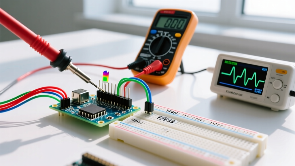
Diagnostic Pro-Tip: Connect a digital multimeter set to 'Min/Max' hold across the Arduino's 5V and GND pins. Command the vehicle to move. If the minimum voltage recorded dips below 4.5V under load, you have a brownout condition.
The Fix: Decoupled Power Rails
- Never power motors from the Arduino 5V pin. The onboard linear regulator can only dissipate about 800mW of heat before thermal shutdown.
- Use a BEC (Battery Eliminator Circuit): Run your main battery pack (e.g., a 2S or 3S Li-ion) directly to the motor driver's high-voltage terminals. Use a dedicated switching buck converter (like the LM2596 module, costing around $2.50) to step the battery voltage down to a clean 5.0V exclusively for the Arduino and RF modules.
- Bulk Capacitance: Solder a 470µF electrolytic capacitor and a 100nF ceramic capacitor in parallel directly across the motor driver's main power input terminals to absorb transient current spikes.
2. Motor Driver Inefficiencies: L298N vs. TB6612FNG
If your Arduino remote control vehicle feels sluggish, lacks torque on inclines, or the motor driver is too hot to touch, you are likely suffering from silicon-level inefficiencies. For years, the L298N H-bridge was the default choice. However, its outdated Bipolar Junction Transistor (BJT) architecture is a major source of diagnostic headaches.
Voltage Drop Comparison Matrix
The L298N introduces a voltage drop of approximately 2.0V to 2.5V across its internal transistors. If you power it with a 2S Li-ion battery (nominal 7.4V, but dropping to 6.4V under load), your motors only receive ~4.4V. According to the Adafruit Motor Selection Guide, running a 6V motor at 4.4V drastically reduces its torque curve and exacerbates stalling.
| Motor Driver IC | Architecture | Voltage Drop | Max Continuous Current | 2026 Market Price (Approx) |
|---|---|---|---|---|
| L298N | BJT (Bipolar) | ~2.0V - 2.5V | 2.0A per channel | $2.00 - $4.00 |
| TB6612FNG | MOSFET | < 0.5V | 1.2A per channel (3.2A peak) | $4.00 - $6.00 |
| DRV8871 | MOSFET | < 0.4V | 3.6A per channel | $5.00 - $8.00 |
Source: Component datasheets and distributor pricing aggregates.
The Fix: Upgrade to MOSFET Drivers
As detailed in the Pololu TB6612FNG documentation, MOSFET-based drivers like the TB6612FNG offer an on-resistance (RDS(on)) of just 0.5Ω, resulting in a negligible voltage drop. Swapping an L298N for a TB6612FNG instantly delivers an extra 1.5V to your motors, resolving sluggishness without requiring a heavier, higher-voltage battery pack.
3. PWM Timer Conflicts in the Sketch
Your hardware is perfect, the power is clean, but your motors emit a high-pitched whine, or your steering servo jitters violently while the drive motors are running. This is a software-level timer collision.
Understanding ATmega328P Hardware Timers
The analogWrite() function generates Pulse Width Modulation (PWM) signals using the microcontroller's internal hardware timers. On the Arduino Uno/Nano (ATmega328P):
- Timer0 (Pins 5 & 6): Operates at ~980 Hz. Critical Warning: Timer0 is also responsible for the
millis(),delay(), andmicros()functions. - Timer1 (Pins 9 & 10): Operates at ~490 Hz (16-bit timer).
- Timer2 (Pins 3 & 11): Operates at ~490 Hz (8-bit timer).
The Diagnostic Trap
If you attempt to change the PWM frequency on Pins 5 or 6 to eliminate the audible motor whine (by altering the prescaler registers), you will unintentionally break all time-based functions in your sketch. Your RC vehicle's steering delays and RF timeout routines will fail catastrophically. Furthermore, if you use the Servo library, it defaults to hijacking Timer1, which will disable PWM on Pins 9 and 10.
The Fix: Strategic Pin Mapping
- Assign your drive motor PWM pins exclusively to Timer2 (Pins 3 and 11).
- If you must use the Servo library for a steering mechanism, be aware that it disables Timer1. Ensure your drive motors are not mapped to Pins 9 or 10.
- For advanced users requiring ultrasonic PWM frequencies (>20kHz) to silence motors, use a dedicated external I2C PWM controller like the PCA9685, completely offloading the timing burden from the ATmega328P.
4. RF Communication Dropouts (HC-12 & HC-05 Modules)
An Arduino remote control vehicle is useless if it loses its tether. The HC-12 (433MHz SI4463 transceiver) and HC-05 (Bluetooth) are the most common wireless modules, yet they are highly susceptible to environmental and electrical noise.
HC-12 AT Mode Lockup
The HC-12 features a SET pin used to enter AT command mode for changing channels and baud rates. If your wiring harness is loose and the SET pin floats LOW during boot, the module enters command mode. It will not transmit or receive serial data, resulting in a complete loss of control.
Solution: Hardwire the SET pin to the Arduino's 5V logic HIGH via a 10kΩ pull-up resistor, or tie it directly to a dedicated GPIO pin that you explicitly set HIGH in the setup() function before initializing the serial port.
Power Supply Noise and Desensitization
Brushed DC motors generate massive electromagnetic interference (EMI) and voltage ripple. If your RF module shares the same 5V rail as the motor logic, the RF module's receiver front-end becomes desensitized, reducing your range from 100 meters to less than 5 meters.
- Isolate the RF VCC: Power the HC-12 or HC-05 from a dedicated 3.3V or 5V LDO regulator (e.g., AMS1117), separate from the motor driver logic supply.
- Physical Separation: Mount the RF module's spring antenna at least 5cm away from the motor driver and battery cables. Solder a 100nF decoupling capacitor directly across the VCC and GND pins on the RF module's breakout board.
Step-by-Step Diagnostic Workflow
When your Arduino remote control vehicle fails, do not rewrite your code immediately. Follow this isolation sequence:
- Elevate and Test Logic: Lift the vehicle off the ground. Connect via USB serial monitor. Send manual movement commands. If it works via USB but fails on battery, you have a power/brownout issue (See Section 1).
- Measure Voltage Drop: Put the vehicle on the ground (under load). Measure the voltage at the motor terminals. If it is more than 1.5V lower than your battery voltage, upgrade your motor driver (See Section 2).
- Verify PWM Mapping: Check your pin assignments against the ATmega328P timer map. Ensure
millis()conflicts are avoided (See Section 3). - RF Loopback Test: Disconnect the motors entirely. Power the Arduino and RF module via a clean USB power bank. Test the wireless range. If range is restored, your previous issue was motor-induced EMI (See Section 4).
By treating your Arduino remote control vehicle as a system of isolated subsystems—power, actuation, computation, and communication—you transform frustrating guessing games into precise, solvable engineering problems.