
The Anatomy of an Arduino 485 Failure
RS-485 remains the undisputed king of long-distance, noise-immune serial communication in industrial and maker environments. Capable of spanning up to 1,200 meters and supporting multiple nodes on a single differential bus, it is the backbone of Modbus networks and remote sensor arrays. However, integrating this standard into a microcontroller environment often leads to frustrating roadblocks. If you are building an Arduino 485 network, you have likely encountered silent failures, garbled hex dumps in your serial monitor, or complete bus lockups.
Unlike point-to-point UART, RS-485 is a multi-drop, half-duplex bus. This means every node shares the same physical wires, and only one device can transmit at a time. Diagnosing Arduino 485 communication errors requires a systematic approach that spans the physical wiring layer, the logic-level timing layer, and the hardware selection process. This guide dives deep into the exact failure modes, specific component values, and microsecond-level code adjustments required to stabilize your RS-485 bus in 2026 and beyond.
The Physical Layer: Wiring, Termination, and Biasing
The most common cause of intermittent Arduino 485 data corruption is improper bus termination and a lack of fail-safe biasing. When no node is transmitting, the differential A and B lines are left floating. In a noisy electrical environment, these floating lines can drift, causing the receiver to interpret phantom voltage spikes as valid start bits, resulting in garbage data.
The 120Ω Termination Rule
According to the Texas Instruments RS-485 design guidelines, the characteristic impedance of standard twisted-pair cable is roughly 120 ohms. To prevent signal reflections that cause bit errors at higher baud rates (typically above 115,200 bps or over long distances), you must place a 120Ω resistor across the A (+) and B (-) lines at the extreme physical ends of the bus. If you have three Arduinos connected in a daisy chain, only the first and last Arduinos should have their onboard or module termination jumpers closed.
Fail-Safe Biasing Resistors
Termination alone does not solve the floating-line issue. You must bias the bus to a known idle state (Logic 1, where A is higher than B). This requires a pull-up resistor on the A line to VCC (usually 5V) and a pull-down resistor on the B line to GND. But what value should you use? The RS-485 standard requires a minimum differential voltage of 200mV to guarantee a valid logic state. Using 560Ω resistors provides a safe biasing current without overloading the driver ICs. Many cheap HW-519 MAX485 modules omit these biasing resistors entirely, forcing you to solder them manually to the master node.
The Logic Layer: DE/RE Pin Toggle Timing
Because RS-485 is half-duplex, the Arduino must control the Driver Enable (DE) and Receiver Enable (RE) pins on the transceiver module. To transmit, you pull DE/RE HIGH; to listen, you pull them LOW. The most insidious Arduino 485 bug occurs when the microcontroller switches the bus to receive mode before the final byte has completely left the hardware shift register.
The Serial.flush() Trap
Most beginner tutorials suggest the following sequence:
- Pull DE/RE HIGH.
- Use
Serial.print()to send data. - Call
Serial.flush(). - Pull DE/RE LOW.
As documented in the official Arduino Serial.flush() reference, this function waits for the transmission of outgoing serial data to complete. However, 'complete' means the software TX buffer is empty. The hardware UART shift register may still be pushing the final byte onto the wire. If you pull DE LOW immediately, you truncate the last byte's stop bit, causing a framing error on the receiving end.
Calculating the Microsecond Delay
To fix this, you must calculate the exact time it takes for one byte to transmit and add a blocking delay. A standard UART frame consists of 10 bits (1 start, 8 data, 1 stop). At 9600 baud, one bit takes 104.16 microseconds. Therefore, one byte takes roughly 1,041 microseconds. Your code must include a delayMicroseconds(1050) immediately after Serial.flush() before pulling the DE/RE pins LOW. At 115,200 baud, this delay shrinks to roughly 87 microseconds. Failing to scale this delay when changing baud rates is a primary source of intermittent packet loss.
Common-Mode Voltage and Ground Loops
RS-485 transceivers like the classic MAX485 are rated for a common-mode voltage range of -7V to +12V. This is the maximum allowable voltage difference between the grounds of the transmitting and receiving nodes. If you connect an Arduino powered by a 24V industrial supply to another Arduino powered by a distant 12V supply, the ground potential difference can easily exceed 12V. When this happens, the internal ESD protection diodes in the MAX485 chip will conduct, eventually frying the IC or causing severe data corruption.
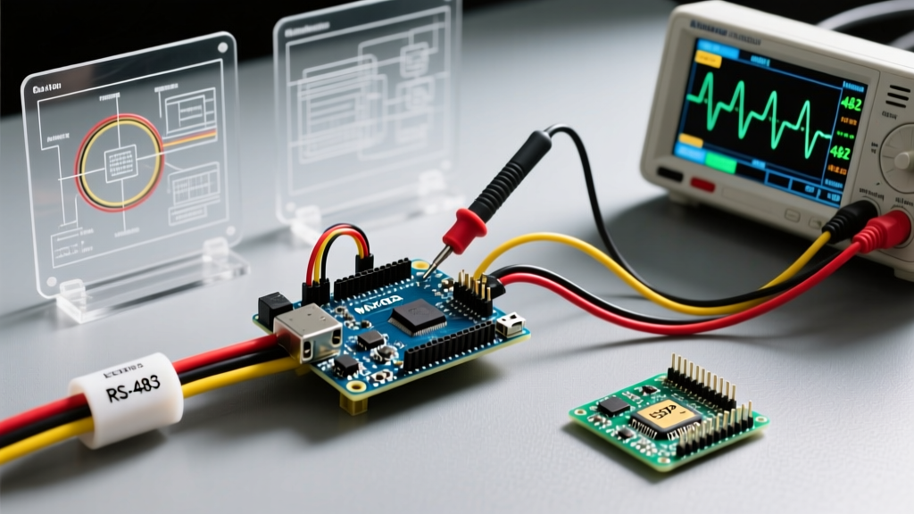
If your Arduino 485 network spans different buildings, power domains, or heavy machinery, you must measure the AC and DC voltage difference between the grounds of your nodes using a multimeter. If the difference exceeds 5V, you must abandon standard modules and switch to isolated RS-485 transceivers.
Diagnostic Matrix: Symptoms and Solutions
Use the following diagnostic table to quickly identify the root cause of your specific Arduino 485 failure mode.
| Symptom | Likely Root Cause | Hardware / Code Fix |
|---|---|---|
| Garbage characters in Serial Monitor | Baud rate mismatch or missing biasing resistors | Add 560Ω pull-up/pull-down on Master; verify crystal oscillator tolerance. |
| Last byte of packet always dropped | DE/RE pin pulled LOW too early | Insert delayMicroseconds() after Serial.flush(). |
| Bus locks up after a few hours | Ground loop exceeding -7V/+12V common-mode limit | Replace MAX485 with an ADUM1201 isolated RS-485 module. |
| Intermittent framing errors | Signal reflection due to missing termination | Solder 120Ω resistor across A and B on the two end nodes. |
| Zero data received, TX LED flashes | A and B wires swapped | Swap the physical A (+) and B (-) twisted pair wires. |
Module Selection: HW-519 vs. Isolated TTL-RS485
Choosing the right transceiver module is critical for long-term reliability. The market is flooded with the red HW-519 module based on the MAX485 or SP485 chips. In 2026, these modules remain incredibly cheap, often retailing for $0.80 to $1.20 each in multi-packs. They are perfectly adequate for short-distance, single-power-domain projects like connecting two Arduinos on the same workbench.
However, for industrial environments, motor control feedback, or outdoor sensor nodes, you must invest in isolated TTL-RS485 modules. These modules typically feature an ADUM1201 digital isolator for the TX/RX/DE lines and a B0505S isolated DC-DC converter to provide a galvanically isolated power supply to the transceiver chip. While they cost between $4.50 and $6.50, they completely eliminate ground loop risks and protect your Arduino's microcontroller from high-voltage transients on the bus.
Expert Tip: When wiring isolated modules, never connect the Arduino's digital ground to the RS-485 isolated ground. The isolation barrier must remain completely unbroken to provide common-mode rejection.
Final Troubleshooting Checklist
Before rewriting your Modbus or custom packet-parsing code, verify your physical layer. Ensure your twisted pair is intact, confirm that only the end nodes have 120Ω termination jumpers engaged, and use an oscilloscope or logic analyzer to verify that your DE/RE pin transitions to LOW precisely one byte-time after the final stop bit is transmitted. Mastering these physical and temporal constraints is the key to deploying bulletproof Arduino 485 networks.