
Achieving flawless LED strip Arduino control requires far more than simply connecting a data pin to a microcontroller. Whether you are building an ambient bias lighting system for a monitor, a large-scale interactive art installation, or a custom IoT dashboard, the underlying physics of addressable LEDs demand strict adherence to power delivery, signal integrity, and timing protocols. In 2026, the market is saturated with high-density COB LED strips and advanced 12V addressable variants like the WS2815, yet the foundational, moving beyond basic tutorials to explore the electrical realities that separate reliable installations from flickering failures.
The Architecture of Addressable vs. Analog Strips
Before writing a single line of code, you must understand the silicon driving your strip. The term "LED strip" encompasses two fundamentally different architectures.
Analog RGB strips (often using 5050 SMD packages) wire all red, green, and blue anodes in parallel. You control the entire strip as a single color using three Arduino PWM pins. Addressable strips, however, embed a microcontroller (IC) inside or adjacent to every LED package. The WS2812B (and its modern waterproof COB equivalents) integrates the IC directly into the LED, requiring only a single data line. The APA102 (DotStar) uses a separate clock and data line, mimicking SPI communication.
| Feature | Analog RGB (5050) | WS2812B / SK6812 | APA102 (DotStar) | WS2815 (12V) |
|---|---|---|---|---|
| Control IC | None | Integrated | External | Integrated |
| Data Pins | 3 (PWM) | 1 | 2 (SPI) | 1 |
| Voltage | 5V / 12V | 5V | 5V | 12V |
| Refresh Rate | MCU PWM (~490Hz) | ~400Hz | ~20kHz | ~400Hz |
| Timing Sensitivity | Low | Critical (800kHz) | Low (Clock driven) | Critical |
Power Topography: Calculating Current and Voltage Drop
The most common point of failure in LED strip Arduino control projects is inadequate power architecture. A standard 5-meter reel of 60 LEDs/m WS2812B strip contains 300 LEDs. If every LED is driven to full white (RGB 255, 255, 255), each LED draws approximately 60mA.
Total Current = 300 LEDs × 0.06A = 18 Amps.
At 5 Volts, this equates to 90 Watts. Attempting to pull this current through a breadboard or the Arduino's onboard 5V regulator will instantly melt your jumper wires and destroy the microcontroller's voltage regulator. You must use a dedicated switching power supply, such as a Mean Well LRS-150-5 (priced around $35 in 2026), which delivers a stable 30A.
Furthermore, the copper traces on standard flexible printed circuit boards (FPCBs) are typically 2oz or 3oz copper, which possess inherent resistance. Pushing 18A through a 5-meter strip will result in severe voltage drop. By the time power reaches the 300th LED, the voltage may sag below 3.5V, causing the LEDs to shift from white to pink or red, and eventually flicker out.
Golden Rule of Power: Never route the main LED power through the Arduino's 5V pin. The onboard linear regulator is typically rated for 800mA maximum, and thermal throttling will occur well before that limit.
The Power Injection Rule of Thumb
- Standard Density (30-60 LEDs/m): Inject power at both ends of a 5-meter strip.
- High Density (90-144 LEDs/m): Inject power every 2.5 meters.
- Wiring Gauge: Use a minimum of 18 AWG silicone wire for injection pigtails, and 14 AWG for the main power bus.
The 3.3V Logic Level Dilemma
As the maker community increasingly adopts 3.3V microcontrollers like the ESP32, Arduino Nano 33 IoT, and Raspberry Pi Pico, logic level shifting has become a mandatory step in reliable LED strip Arduino control. The WS2812B datasheet specifies the Input High Voltage ($V_{IH}$) as $0.7 \times V_{DD}$. If your LED strip is powered by 5V, the data line must reach at least 3.5V to register as a logical 'HIGH'.
A 3.3V microcontroller falls short of this threshold, resulting in the first LED in the chain misinterpreting bits, which cascades into random color noise down the entire strip. The SparkFun Logic Level Tutorial outlines several methods for bridging this gap, but the most robust solution for high-speed 800kHz signals is the 74AHCT125 or SN74LVC1T45 level shifter IC. These chips translate the 3.3V logic to a clean 5V square wave without introducing the propagation delay inherent in MOSFET-based bidirectional shifters.
Essential Passive Components for Signal Integrity
To protect the microcontroller and ensure signal fidelity, two passive components are non-negotiable in professional LED strip Arduino control wiring:
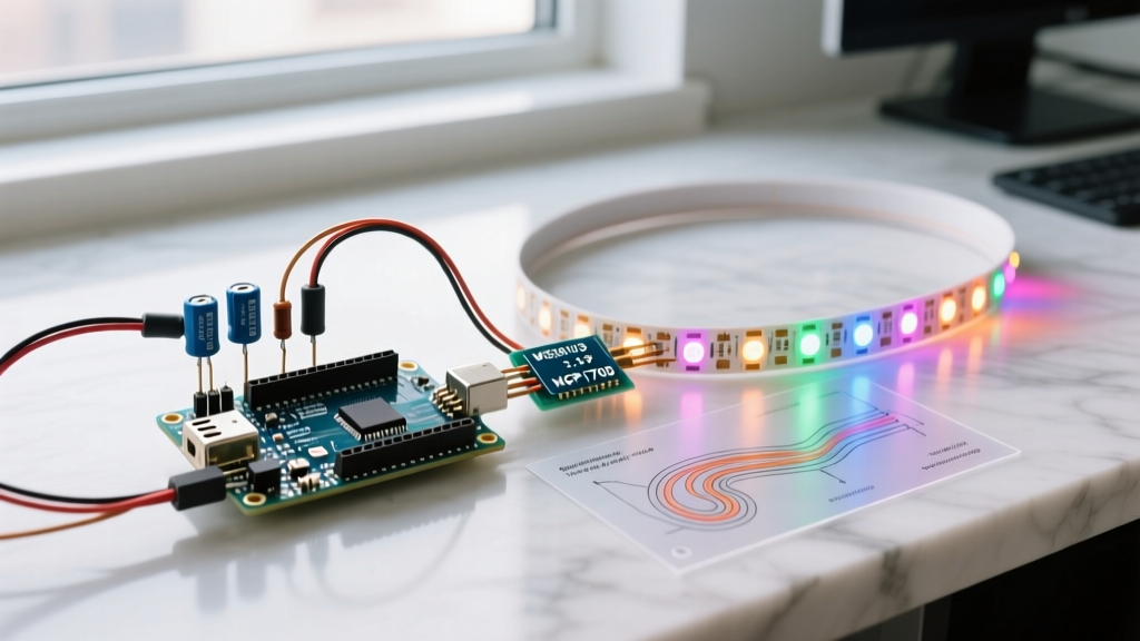
- The Data Line Resistor (330Ω to 470Ω): Placed in series with the DIN pin of the first LED. This resistor provides impedance matching, reducing high-frequency ringing on long data wires, and protects the LED's internal data pin from inductive voltage spikes if the strip is disconnected while powered.
- The Bulk Capacitor (1000µF, 10V+ Low-ESR): Placed across the VCC and GND rails at the power injection point. When an LED strip transitions instantly from black to full white, the sudden inrush of current can cause a transient voltage sag that triggers the microcontroller brown-out reset. A low Equivalent Series Resistance (ESR) electrolytic capacitor acts as a local energy reservoir to absorb this spike.
Software Timing: FastLED vs. Adafruit NeoPixel
Controlling WS2812B strips requires precise timing. A logical '1' is represented by a high pulse of 800ns, and a '0' by a 400ns pulse. Any deviation greater than 150ns can corrupt the data stream. The Adafruit NeoPixel Überguide provides excellent foundational code, but its standard implementation disables all microcontroller interrupts while pushing data to the strip. On an ESP32 or WiFi-enabled Arduino, this interrupt blocking can cause WiFi stack crashes and dropped packets.
In 2026, FastLED Library Documentation, the library automatically compensates for human eye perception using non-linear PWM scaling, and it allows you to define #define FASTLED_ALLOW_INTERRUPTS 0 if you need strict timing guarantees at the cost of dropping WiFi packets.
Conversely, if you are using APA102 (DotStar) strips, timing is governed by a hardware clock line (SPI). This completely eliminates the need for cycle-counting assembly code, freeing the Arduino to handle background tasks, serial communication, and WiFi stacks without corrupting the LED data stream.
Diagnostic Matrix for Common Hardware Failures
Even with meticulous planning, environmental factors and component tolerances can introduce anomalies. Use this troubleshooting matrix to diagnose issues in the field:
| Symptom | Root Cause | Engineering Solution |
|---|---|---|
| First LED flickers or shows random colors | Data line noise or missing termination resistor | Solder a 330Ω-470Ω resistor directly to the DIN pad of the first LED. |
| Colors shift to pink/green down the strip | Severe voltage drop across FPCB traces | Inject 5V and GND at the midpoint and end of the strip using 18 AWG wire. |
| Entire strip displays random noise | 3.3V MCU failing to meet WS2812B $V_{IH}$ threshold | Route the data line through a 74AHCT125 logic level shifter powered by 5V. |
| LEDs randomly reset during high-brightness scenes | Transient voltage sag exceeding IC brown-out threshold | Add a 1000µF low-ESR capacitor at the power injection point. |
Mastering LED strip Arduino control is ultimately an exercise in electrical discipline. By respecting current limits, maintaining signal integrity through proper logic shifting, and selecting the correct software library for your specific microcontroller architecture, you can build lighting systems that are both visually stunning and electrically bulletproof.