
The Bottleneck: Why Standard Keypad Wiring Slows You Down
When prototyping an Arduino and keypad interface, most makers default to the standard 4x4 membrane matrix. While inexpensive (typically $2 to $4 in 2026), these keypads require eight digital I/O pins to function. On an Arduino Uno or Nano, which only offers 14 digital pins, dedicating over 50% of your available I/O to a single input device creates an immediate workflow bottleneck. This pin-starvation forces you to compromise on adding essential peripherals like I2C sensors, SPI displays, or motor drivers later in the development cycle.
Furthermore, the software workflow often suffers. Beginners frequently rely on blocking delay() functions or inefficient polling loops to handle switch debouncing. This approach locks up the microcontroller, causing missed sensor readings and sluggish UI responses. To truly optimize your development workflow, you must rethink both the hardware topology and the software architecture of your matrix scanning routines.
Hardware Workflow: Upgrading to I2C Port Expanders
The most effective way to streamline your hardware workflow is to decouple the keypad from the microcontroller's native GPIO pins using an I2C port expander. By shifting the matrix scanning to a dedicated IC, you reduce the Arduino connection to just two wires (SDA and SCL), freeing up critical pins for your core application logic.
Choosing the Right Expander IC
There are two primary workhorses for I2C expansion in the maker ecosystem:
- PCF8574 (8-bit): Ideal for 3x3 or 3x4 matrices. According to the NXP PCF8574 datasheet, this chip features quasi-bidirectional I/O with internal pull-ups, simplifying the wiring. A bare SOIC-16 chip costs around $0.80, while a pre-assembled breakout module runs $1.20 to $1.80.
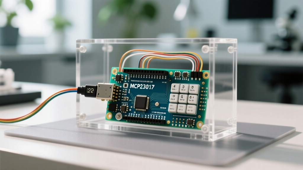
- MCP23017 (16-bit): The gold standard for full 4x4 or even 4x5 matrices. As detailed on the Microchip MCP23017 product page, it offers configurable interrupt pins (INTA/INTB), allowing the Arduino to sleep and only wake when a key is pressed—a massive workflow optimization for battery-powered projects. Modules cost roughly $2.50 to $3.50.
Pro-Tip for I2C Stability: Always ensure your I2C bus has 4.7kΩ pull-up resistors on both SDA and SCL lines. While many Arduino boards have weak internal pull-ups (20kΩ–50kΩ), they are insufficient for reliable I2C communication at 400kHz, especially when using longer Dupont wires on a breadboard.
Component & Workflow Comparison Matrix
| Integration Method | Pins Used | Est. Cost (2026) | CPU Overhead | Best Use Case |
|---|---|---|---|---|
| Direct GPIO Wiring | 8 Digital | $3.00 (Keypad only) | High (Polling) | Simple, single-purpose toys |
| PCF8574 I2C Expander | 2 (I2C) | $4.50 (Keypad + IC) | Medium (Polling) | Standard UI dashboards |
| MCP23017 + Interrupts | 2 (I2C) + 1 (INT) | $6.00 (Keypad + IC) | Low (Event-driven) | Battery-powered / IoT devices |
| Dedicated LED/Key Driver (e.g., IS31FL3731) | 2 (I2C) | $12.00+ | Low (Hardware scan) | Complex backlit control panels |
Software Workflow: Non-Blocking Matrix Scanning
The most common trap when coding an Arduino and keypad project is using the standard Keypad.h library in a blocking manner, or writing custom delay() loops to debounce mechanical switch bounce. Blocking code halts the main loop, which is catastrophic if your project simultaneously manages WS2812 LED animations, PID temperature control, or WebSocket communications.
Implementing a millis() Based State Machine
To optimize your software workflow, adopt a non-blocking polling strategy. By leveraging the millis() function, as demonstrated in Arduino's BlinkWithoutDelay documentation, you can scan the matrix every 20 milliseconds without pausing the rest of your sketch.
Here is the conceptual workflow for a non-blocking scanner:
- Initialize State: Set all column pins HIGH (or use internal pull-ups) and row pins LOW.
- Check Timer: In the main
loop(), check ifcurrentMillis - previousScanMillis >= 20. - Scan Rows/Cols: Iterate through the columns, pulling one LOW at a time, and read the row states.
- Debounce Logic: Do not register a keypress immediately. Store the raw scan in a buffer. Only register a 'confirmed press' when the same key reads stable for 3 consecutive scans (60ms total).
- Trigger Event: Fire your application logic (e.g., updating a display or sending an MQTT payload) only on the confirmed state change.
This event-driven software architecture ensures your microcontroller spends less than 1% of its CPU cycles scanning the keypad, leaving the rest of the processing power for your core application.
The Ghosting Phenomenon and Hardware Diodes
A frequent edge case that derails keypad workflows is 'ghosting' or 'key masking.' This occurs when three keys forming a rectangle on the matrix are pressed simultaneously, causing the controller to register a false fourth keypress. If your project requires N-key rollover (NKRO) or complex multi-key shortcuts, software cannot fix this hardware limitation.
The Solution: Integrate 1N4148 switching diodes in series with every switch in your matrix. The diodes enforce unidirectional current flow, completely eliminating ghosting paths. In 2026, a reel of 10,000 SMD 1N4148 diodes (SOD-323 package) costs roughly $15, making them an essential, low-cost addition to your custom PCB workflow.
Transitioning from Prototyping to Production
Optimizing your workflow also means planning for the transition from a messy breadboard to a manufactured PCB. Membrane keypads are excellent for enclosures requiring water resistance, but they offer poor tactile feedback and rely on fragile ZIF connectors.
For production-grade control panels, transition to a matrix of SMD tactile switches (such as the C&K Components PTS645 series). Pair these with an MCP23017 expander and a 74HC595 shift register if you also need to drive indicator LEDs. By designing a modular daughterboard for your keypad matrix that connects to the main microcontroller via a standardized 4-pin JST-SH connector (VCC, GND, SDA, SCL), you can iterate on your UI layout without redesigning the main logic board.
Frequently Asked Questions (FAQ)
Can I rely on the Arduino's internal pull-up resistors for the keypad matrix?
While the ATmega328P features internal pull-ups (typically 20kΩ to 50kΩ), they are relatively weak. In environments with high electromagnetic interference (EMI), such as near relays or stepper motors, these weak pull-ups can lead to false triggers. For a robust workflow, disable internal pull-ups and use external 10kΩ resistors on the row lines to ensure crisp, noise-immune logic HIGH states.
How do I handle I2C address conflicts when using multiple PCF8574 expanders?
The standard PCF8574 allows you to set the last three bits of the I2C address via A0, A1, and A2 pins, giving you 8 unique addresses (0x20 to 0x27). If you need more, use the PCF8574A variant, which occupies a different base address range (0x38 to 0x3F). This allows up to 16 separate 8-bit matrices on a single I2C bus, perfect for complex industrial control panels.
Is it worth using a dedicated keypad encoder IC instead of an I2C expander?
For most maker and prosumer projects, no. Dedicated encoder ICs (like the old MM74C922) are largely obsolete, expensive, and difficult to source in 2026. An MCP23017 or PCF8574 costs a fraction of the price, is widely available, and offers vastly more flexibility since the I/O pins can be repurposed for other tasks via software if your project requirements change mid-development.