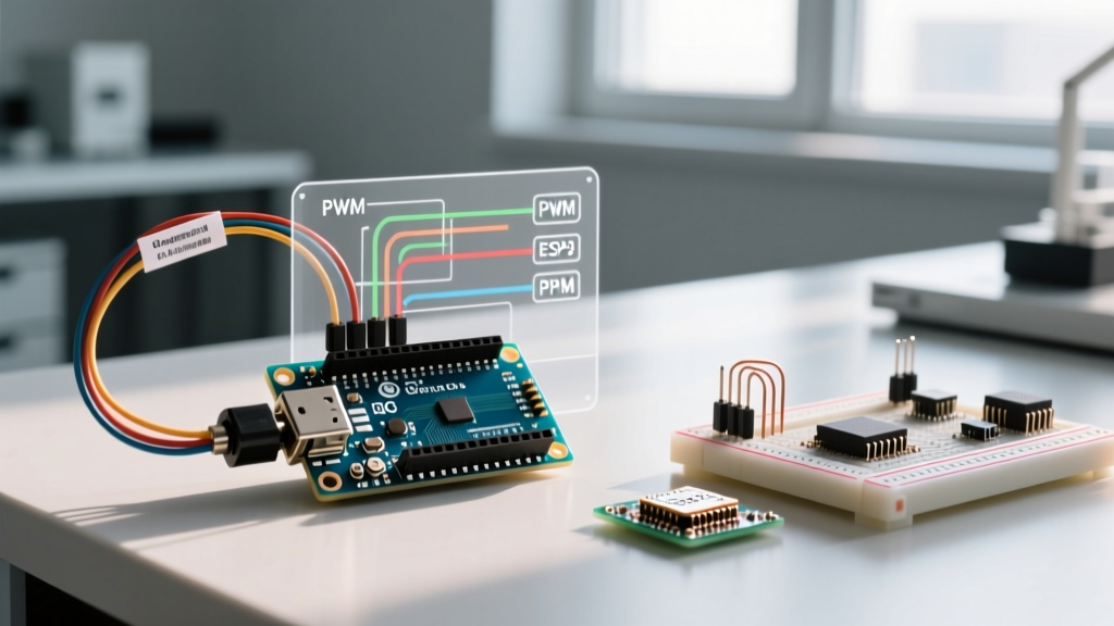

Bridging the Gap: Microcontrollers and Hobby RC Systems
Integrating an Arduino into a radio-controlled platform—whether you are building an autonomous rover, a custom RC boat, or a DIY flight controller—requires precise translation of hobby-grade radio signals into microcontroller logic. The term Arduino RC encompasses a wide variety of projects, but they all share a fundamental hurdle: accurately decoding the receiver's output without bogging down the microcontroller's main loop.
In this comprehensive configuration guide, we will explore the exact hardware setups, signal timing mathematics, and C++ configuration strategies required to read standard PWM (Pulse Width Modulation) and PPM (Pulse Position Modulation) signals. By the end of this guide, you will know how to implement non-blocking interrupt service routines (ISRs) and configure critical safety failsafes.
Understanding RC Signal Protocols
Before writing any code, it is vital to understand the electrical characteristics of standard RC receiver outputs. Most entry-level to mid-range receivers (such as the popular FlySky FS-iA6B or the FrSky XM+) output standard hobby PWM signals on individual pins.
The 50Hz PWM Standard
Standard RC PWM is not the same as the PWM used to dim LEDs or control motor speeds via analogWrite(). Instead, it is a time-based protocol where the width of the high pulse dictates the servo position or throttle value.
- Frequency: 50Hz (one pulse every 20 milliseconds, or 20,000µs).
- Minimum Pulse (1000µs): Typically represents full left steering or minimum throttle.
- Center Pulse (1500µs): Neutral position or stick center.
- Maximum Pulse (2000µs): Full right steering or maximum throttle.
According to the SparkFun PWM Tutorial, while standard PWM varies duty cycles to simulate analog voltages, RC PWM strictly uses the absolute time-domain width of the pulse to encode data. This distinction is critical when configuring your Arduino's timers.
Hardware Configuration and Wiring
For this guide, we will use the FlySky FS-iA6B receiver, a staple in the DIY RC community due to its low cost (approximately $15) and dual-output capability (PWM and PPM). You will need an Arduino Uno or Nano (ATmega328P based), jumper wires, and a 5V power supply or Battery Eliminator Circuit (BEC).
The Golden Rule of RC Wiring: Common Ground
The most frequent cause of erratic Arduino RC behavior is a missing common ground. The receiver's GND pin must be connected directly to the Arduino's GND pin. If the receiver is powered by an external ESC (Electronic Speed Controller) BEC, and the Arduino is powered via USB, you must bridge the BEC GND and Arduino GND. Without this shared reference plane, the Arduino will read floating voltages, resulting in wild, unpredictable pulse readings.
Method 1: The Blocking Approach (pulseIn)
For beginners testing a single channel, the Arduino IDE provides a built-in function. As documented in the official Arduino pulseIn() reference, this function waits for a pin to go HIGH, starts timing, and stops when it goes LOW.
Configuration Logic:
int ch1_pin = 2;
unsigned long ch1_value;

void setup() {
  Serial.begin(115200);
  pinMode(ch1_pin, INPUT);
}

void loop() {
  // Timeout set to 25000 microseconds (25ms)
  ch1_value = pulseIn(ch1_pin, HIGH, 25000);
  Serial.println(ch1_value);
}
Expert Warning: Never use pulseIn() for multi-channel Arduino RC projects. Because the function is blocking, reading six channels sequentially can stall your main loop for up to 150 milliseconds. This completely destroys the timing requirements for PID control loops, sensor fusion (like MPU6050 IMU reads), and motor commutation.
Method 2: Non-Blocking Interrupt-Driven PWM
To achieve professional-grade Arduino RC integration, you must use hardware interrupts. By utilizing the attachInterrupt() function, the Arduino can timestamp the exact microsecond a pin changes state, allowing the main loop to run thousands of times per second while signal decoding happens in the background.
Configuring the ISR (Interrupt Service Routine)
On an Arduino Uno, pins 2 and 3 support external interrupts. We configure the interrupt to trigger on the CHANGE state (both rising and falling edges).
volatile unsigned long rising_edge = 0;
volatile unsigned long channel_1 = 1500; // Default center

void setup() {
  pinMode(2, INPUT_PULLUP);
  attachInterrupt(digitalPinToInterrupt(2), read_pwm, CHANGE);
}

void read_pwm() {
  if (digitalRead(2) == HIGH) {
    rising_edge = micros(); // Timestamp the rising edge
  } else {
    if (rising_edge > 0) {
      channel_1 = micros() - rising_edge; // Calculate pulse width
    }
  }
}
This configuration guarantees that pulse measurement takes less than 5 microseconds of CPU time, leaving the rest of the 20ms frame entirely free for your robotics logic.
Method 3: Decoding PPM (Pulse Position Modulation)
Wiring 8 individual PWM channels to an Arduino is cumbersome and uses too many I/O pins. PPM solves this by multiplexing all channels onto a single wire. The FlySky FS-iA6B outputs PPM on its dedicated 'Signal' or 'Batt' pin (depending on the specific hardware revision and jumper settings).
The Mathematics of a PPM Frame
A PPM stream consists of a series of high pulses separated by low gaps. The data is not in the pulse width itself, but in the time between rising edges.
- Sync Pulse: A long high state (typically >3000µs) indicates the end of one frame and the start of the next.
- Channel Pulses: The time from one rising edge to the next represents the channel value (1000µs to 2000µs).
- Frame Rate Math: 8 channels × 2000µs max = 16,000µs. Add a 3000µs sync pulse, and the total frame takes 19,000µs (19ms). This fits perfectly inside the standard 20ms (50Hz) RC window.
To decode this, you configure a single Pin Change Interrupt (PCINT) or standard external interrupt. Inside the ISR, you measure the time between consecutive rising edges. If the gap exceeds 3000µs, you reset your channel counter to zero. Otherwise, you store the measured interval into an array indexed by the current channel counter.
Protocol Comparison Matrix
When designing your Arduino RC project, choose the protocol that best fits your hardware constraints and processing needs.
| Protocol | Wires Required | Max Channels | Refresh Rate | Arduino Decoding Complexity |
|---|---|---|---|---|
| Standard PWM | 1 per channel + GND | 6-8 (Typical) | 50Hz (20ms) | Low (Interrupts) |
| PPM | 1 total + GND | 8-12 | 50Hz (20ms) | Medium (State Machine ISR) |
| SBUS | 1 (UART RX) + GND | 16 + 2 Digital | 100Hz - 140Hz | High (Inverted UART, 100k baud) |
| CRSF (Crossfire) | 1 (UART RX/TX) + GND | 16+ | 150Hz - 500Hz | Very High (Packet parsing, CRC) |
Critical Safety: Configuring Failsafes
In any Arduino RC vehicle, signal loss is inevitable. If your RC transmitter loses connection, the receiver must output a predefined, safe state. If you fail to configure this, your Arduino might read the last known throttle value (e.g., 2000µs / full forward) and drive your rover into a wall or off a table.
Setting Failsafe on the FlySky FS-i6 Transmitter
- Power on your transmitter and bind it to the receiver.
- Navigate to System Setup > RX Setup > Failsafe.
- Set your Throttle channel (usually CH3) to -100%. This forces the receiver to output approximately 990µs upon signal loss.
- Set your Steering/Aileron channels to 0% (Center / 1500µs).
- Press and hold the OK button to save the configuration to the receiver's non-volatile memory.
Arduino Code Implementation: In your main loop, always include a boundary check. If channel_1 < 1050, trigger your software emergency stop routine. This accounts for both the transmitter failsafe and actual receiver power loss.
Troubleshooting Edge Cases and Signal Jitter
Even with perfect code, environmental factors can degrade Arduino RC signal integrity. Here is how to diagnose and fix common issues:
1. Microsecond Jitter
If your serial monitor shows values bouncing between 1495µs and 1505µs while the sticks are perfectly still, you are experiencing jitter. This is rarely an Arduino fault; it is usually caused by voltage ripple from a cheap BEC or long, unshielded servo wires acting as antennas.
The Fix: Solder a 100nF (0.1µF) ceramic capacitor directly across the VCC and GND pins on the receiver's output header. This creates a local high-frequency filter that smooths out voltage spikes, instantly stabilizing the Arduino's internal timer readings.
2. The 5V vs 3.3V Logic Mismatch
Standard RC receivers output 3.3V logic highs, even when powered by a 5V BEC. The ATmega328P on an Arduino Uno requires a minimum of 3.0V to reliably register a HIGH on a 5V system, which usually works. However, if you are using a 3.3V Arduino (like the Arduino Due or a custom ESP32 integration), feeding a 5V PWM signal from an older receiver into a 3.3V GPIO pin will permanently destroy the microcontroller. Always use a bidirectional logic level converter or a simple voltage divider (e.g., 10kΩ and 20kΩ resistors) when interfacing 5V RC gear with 3.3V logic boards.
Conclusion
Mastering Arduino RC configuration requires moving beyond basic blocking functions and embracing hardware interrupts. By understanding the strict 1000-2000µs timing windows, properly wiring common grounds, and implementing rigorous failsafe protocols, you can build highly responsive, safe, and autonomous RC platforms. Whether you choose the simplicity of multi-wire PWM or the elegance of single-wire PPM, the interrupt-driven approach ensures your microcontroller remains free to handle the complex robotics tasks at hand.