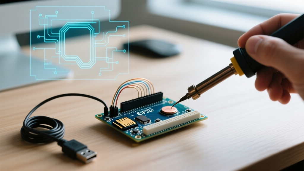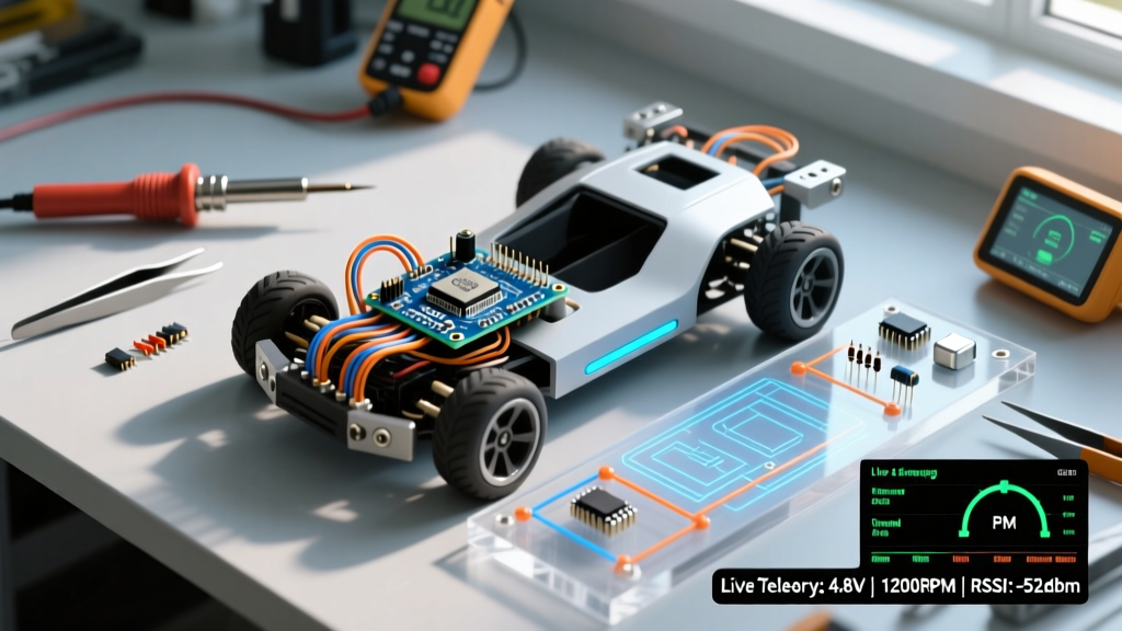

Rethinking the Arduino RC Car Prototyping Pipeline
The traditional approach to building an arduino rc car often follows a chaotic trajectory: a tangled mess of jumper wires on a breadboard, a monolithic sketch riddled with blocking delay() functions, and hours of blind troubleshooting when the vehicle inevitably stalls on the track. As of 2026, with the maker ecosystem saturated with high-performance, low-cost microcontrollers and advanced motor drivers, this outdated workflow is no longer necessary.
Optimizing your build workflow is about shifting from reactive debugging to proactive, modular engineering. By separating your hardware into distinct power and logic planes, staging your firmware deployment, and integrating live telemetry from day one, you can reduce prototyping time by up to 60%. This guide details a professional-grade workflow for designing, coding, and debugging an Arduino-based RC vehicle.
Phase 1: Hardware Modularity and Power Distribution
The most common point of failure in amateur RC builds is power starvation and signal noise caused by poor wiring topology. Breadboards cannot handle the vibration of an RC chassis, and daisy-chained ground wires create ground loops that introduce jitter into your steering servos.
Implementing a Star Ground and Dual-Plane Architecture
To optimize hardware reliability, abandon the single-rail power distribution model. Instead, implement a dual-plane architecture:
- High-Current Plane (7.4V - 8.4V): Powered by a 2S LiPo battery (e.g., a 1500mAh 50C pack, roughly $18). This plane feeds the motor driver and high-torque steering servo directly.
- Logic Plane (5V / 3.3V): Powered by a dedicated buck converter. Do not rely on the microcontroller's onboard linear regulator, which will thermally throttle when subjected to 8.4V inputs and high servo currents.
Pro-Tip: Use a star grounding topology. Connect the battery ground, motor driver ground, servo ground, and microcontroller ground to a single, centralized terminal block or copper pour. This prevents high-current motor spikes from shifting the logic ground reference, which is the primary cause of erratic RC receiver behavior.
Component Selection: Ditching the L298N
If your workflow still includes the L298N motor driver, it is time to upgrade. The L298N utilizes outdated bipolar junction transistor (BJT) technology, resulting in a massive voltage drop (up to 2V) and significant heat generation. Modern workflows demand MOSFET-based drivers.
| Driver Model | Continuous Current | Voltage Drop | Prototyping Efficiency | Approx. Cost |
|---|---|---|---|---|
| L298N (Legacy) | 2.0A (Total) | ~2.0V | Low (Bulky, high heat) | $4.00 |
| TB6612FNG | 1.2A per ch (3.2A peak) | ~0.5V | High (Compact, efficient) | $5.95 |
| DRV8833 | 1.5A per ch | ~0.6V | Medium (Requires breakout) | $3.50 |
For a standard 1:16 scale RC car, the TB6612FNG offers the best balance of thermal efficiency and footprint. Furthermore, standardizing on JST-XH (2.54mm) connectors for power and JST-PH (2.0mm) for signals allows you to swap out burnt motors or upgrade microcontrollers in seconds without touching a soldering iron.
Phase 2: Staged Firmware Development
Writing a complete RC car sketch in one sitting is a recipe for logic errors. An optimized workflow breaks firmware development into three isolated, testable stages. This ensures that when a bug occurs, you know exactly which subsystem is at fault.
Stage 1: Open-Loop Motor Validation
Before connecting the RC receiver, write a simple state machine to validate the motor driver. Use a non-blocking timing approach rather than delay(). The BlinkWithoutDelay paradigm is essential here. By using millis() to toggle motor directions every 2 seconds, you verify wiring, PWM frequency, and power delivery without tying up the CPU.
Stage 2: Interrupt-Driven RC Signal Parsing
The most critical bottleneck in Arduino RC car code is reading the PWM signals from the RC receiver. Beginners often use pulseIn(), a blocking function that halts the microcontroller until a pulse completes. If you are reading 4 channels (steering, throttle, aux 1, aux 2), pulseIn() can block your main loop for up to 12 milliseconds—causing severe latency in motor control and telemetry.
The Optimized Solution: Use hardware interrupts. By leveraging attachInterrupt(), you can measure pulse widths in the background via an Interrupt Service Routine (ISR).
volatile unsigned long last_micros;
volatile int throttle_pulse;

void throttleISR() {
  if (digitalRead(THROTTLE_PIN) == HIGH) {
    last_micros = micros();
  } else {
    throttle_pulse = micros() - last_micros;
  }
}
This ISR executes in microseconds, ensuring your main loop remains free to handle complex kinematics, traction control algorithms, or wireless telemetry.
Stage 3: Closed-Loop Control and Telemetry
Once motor control and signal parsing are verified independently, integrate them using a PID controller for smooth acceleration curves. At this stage, you should also implement live telemetry to monitor the vehicle's internal state.
Phase 3: Telemetry-Driven Debugging
You cannot optimize what you cannot measure. In 2026, relying on an Arduino Uno and a USB cable for debugging an RC car is impractical. The modern workflow utilizes the ESP32-S3 (costing roughly $5-$7 per module) for its dual-core 240MHz processing, native USB, and built-in Wi-Fi/Bluetooth.
Setting Up a UDP Telemetry Stream
Instead of guessing why your car is stuttering mid-corner, stream live data to your laptop or smartphone. By configuring the ESP32 as a UDP server on your local Wi-Fi network, you can broadcast a JSON or CSV payload every 50ms containing:
- Raw RC Receiver Pulse Widths (to detect signal dropout)
- Calculated Motor PWM Duty Cycle
- Battery Voltage (via a simple resistor divider on an ADC pin)
- IMU Orientation (if using an MPU6050 for traction control)
Using a tool like the Arduino Serial Plotter (via Bluetooth SPP) or a custom Python dashboard (via UDP), you can visualize throttle input versus actual motor output in real-time. This immediately reveals issues like dead-zones in your RC transmitter or thermal throttling in your motor driver.
Troubleshooting Matrix: Edge Cases and Failure Modes
Even with an optimized workflow, edge cases will emerge during track testing. Use this matrix to rapidly diagnose anomalous behavior without resorting to trial-and-error.
| Symptom | Probable Root Cause | Optimized Diagnostic Step |
|---|---|---|
| Microcontroller resets during hard acceleration | Logic plane brownout due to voltage sag on the 2S LiPo | Log battery voltage via ADC at 100Hz. If V_batt drops below 6.0V under load, upgrade to a battery with a higher C-rating (e.g., 50C to 75C). |
| Steering servo jitters erratically | Ground loop noise or 5V rail ripple from the buck converter | Measure the 5V logic rail with an oscilloscope. Add a 100µF electrolytic capacitor and a 0.1µF ceramic capacitor in parallel at the servo power input. |
| RC signal drops out beyond 5 meters | Carbon fiber chassis blocking 2.4GHz RF, or antenna placed near motor noise | Reroute the receiver antenna vertically away from the motor driver. Use an external RP-SMA antenna extension if the chassis is RF-opaque. |
| Motor PWM output feels 'laggy' | Main loop blocked by I2C IMU reads or Serial printing | Move I2C reads to Core 0 (on ESP32) using FreeRTOS, or reduce Serial baud rate/telemetry frequency to 20Hz. |
Conclusion: The ROI of an Optimized Workflow
Transitioning to a modular, staged workflow for your arduino rc car project requires a slight upfront investment in time and specialized connectors like JST harnesses and buck converters. However, the return on investment is immediate. By eliminating blocking code, isolating hardware subsystems, and leveraging live telemetry, you transform the debugging process from a frustrating guessing game into a data-driven science. Whether you are building a high-speed drift car or an autonomous rover, this 2026-standard pipeline ensures your microcontroller spends its cycles calculating kinematics, not waiting on I/O.