
The Hidden Costs of the 'Standard' Button Tutorial
If you search for how to wire button arduino circuits, 90% of the tutorials will instruct you to use a 10kΩ external pull-down resistor, wire one side of the switch to 5V, and read the digital pin. While this works for a five-minute breadboard test, it is a highly inefficient workflow for serious prototyping or production scaling. Relying on external pull-down resistors increases your Bill of Materials (BOM), consumes valuable breadboard or PCB real estate, and introduces unnecessary points of failure.
In 2026, embedded development workflows demand optimization. Whether you are building a custom macro pad, an industrial control interface, or an IoT sensor node, transitioning from beginner wiring habits to professional input architectures will save you assembly time, reduce component costs, and drastically improve field reliability. This guide re-engineers the standard button wiring process into a streamlined, production-ready workflow.
Workflow Shift 1: Eliminating External Resistors with Internal Pull-Ups
The most immediate optimization in button wiring is leveraging the microcontroller's internal pull-up resistors. The ATmega328P (found in the Arduino UNO R3 and Nano) features internal pull-up resistors ranging from 20kΩ to 50kΩ on all digital I/O pins. Modern boards like the Arduino UNO R4 Minima (RA4M1) and ESP32-S3 also feature highly configurable internal pull-ups.
The Optimized Wiring Topology
By using internal pull-ups, you reduce the wiring to just two connections per button:
- Terminal 1: Connect directly to the microcontroller's Digital Pin.
- Terminal 2: Connect directly to the microcontroller's GND.
In your sketch, you initialize the pin using pinMode(buttonPin, INPUT_PULLUP);. According to the official Arduino digital pins documentation, this connects the internal resistor to the 3.3V or 5V rail, keeping the pin HIGH by default. When the button is pressed, it bridges the pin to GND, pulling the state LOW.
Workflow Advantage: This inversion of logic (LOW = pressed) eliminates the need for external resistors entirely. In a 50-unit production run with 4 buttons each, you save 200 resistors, 400 jumper wire connections, and roughly 3 hours of manual assembly time.
Critical Edge Case: ESP32 Strapping Pins
When applying this workflow to ESP32-based Arduino boards, you must avoid GPIOs tied to boot strapping. For example, GPIO 0 and GPIO 2 on the original ESP32 dictate boot modes. Wiring a button that pulls these pins LOW during power-up will cause the microcontroller to enter flash download mode instead of executing your sketch. Always consult the specific datasheet for your ESP32 variant to map safe input pins.
Workflow Shift 2: Strategic Debouncing Architectures
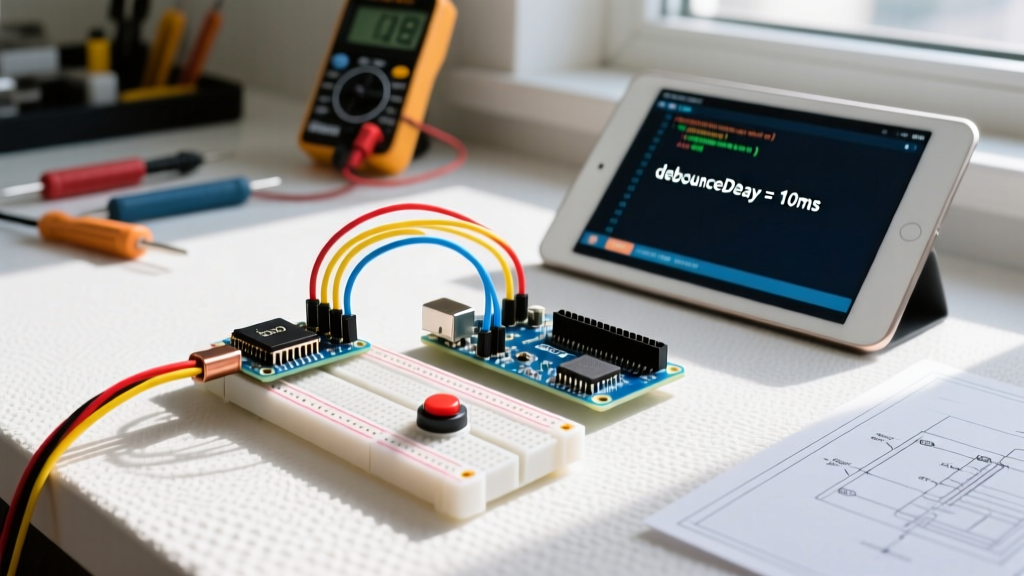
Mechanical switch contacts do not close cleanly; they physically bounce, creating rapid HIGH/LOW transitions that last anywhere from 1ms to 20ms. If your Arduino polls the pin during this window, a single press registers as multiple inputs. Optimizing your debounce workflow depends on your deployment environment.
The Software-First Approach (Rapid Prototyping)
For 80% of maker projects and non-safety-critical prototypes, software debouncing is the most efficient workflow. Rather than writing custom millis() delay logic, integrate the Bounce2 library by Thomas Ouellet Fredericks. It handles state-change detection and timing in the background without blocking the main loop.
Implementation: Initialize the Bounce object, attach it to your INPUT_PULLUP pin, and use debouncer.fell() to trigger actions only on the exact moment the button is physically pressed, ignoring the bounce noise.
The Hardware Approach (High-Noise Environments)
If your Arduino is mounted near inductive loads (relays, stepper motors, or solenoids), electromagnetic interference (EMI) can induce false triggers that software debouncing cannot reliably filter. In these scenarios, a hardware RC (Resistor-Capacitor) filter combined with a Schmitt trigger is mandatory.
- RC Network: Place a 10kΩ resistor in series with the switch output and a 100nF (0.1µF) MLCC capacitor to GND. This creates a time constant ($\tau = R \times C$) of 1ms, smoothing the physical bounce.
- Schmitt Trigger: Route the RC signal through a 74HC14 hex inverting Schmitt trigger IC. This provides hysteresis, converting the slow RC voltage curve into a razor-sharp digital edge that the Arduino can read flawlessly.
For a deeper dive into the physics of contact bounce, All About Circuits provides an excellent technical breakdown of both hardware and software mitigation strategies.
Component Selection Matrix for Production Scaling
Choosing the right physical switch is just as critical as the wiring topology. The DigiKey TechZone guide on tactile switches highlights that lifecycle ratings and actuation forces dictate long-term reliability. Below is a decision matrix for optimizing your BOM based on the project's end-use environment.
| Switch Category | Recommended Model | Lifecycle (Presses) | Approx. Unit Cost (2026) | Best Use Case |
|---|---|---|---|---|
| PCB Tactile | C&K PTS645 Series | 100,000 | $0.12 - $0.18 | Internal PCBs, consumer electronics, macro pads. |
| Panel Mount | Schurter MTP Series | 500,000 | $2.40 - $3.50 | Industrial control panels, enclosed instruments. |
| Piezo Solid State | EAO Series 45 | 20,000,000+ | $18.50 - $25.00 | Vandal-proof public interfaces, medical devices. |
| Capacitive Touch | Microchip CAP1188 | Infinite | $1.10 (IC only) | Sealed enclosures, waterproof outdoor interfaces. |
Enclosure Integration: Ditching Dupont Wires
The final bottleneck in button wiring workflows is the physical interconnect between the enclosure-mounted switch and the Arduino. Standard 2.54mm Dupont jumper wires are notorious for vibrating loose, oxidizing, and causing intermittent faults in field deployments.
Transitioning to Locking Connectors
To optimize your assembly workflow and ensure field reliability, transition to locking wire-to-board connectors:
- JST-XH (2.54mm Pitch): The industry standard for maker-to-prosumer transitions. They feature a positive locking friction ramp that prevents accidental disconnection. Ideal for panel-mount buttons wired to an Arduino shield.
- Molex PicoBlade (1.25mm Pitch): Use these when space is at a premium inside compact, 3D-printed enclosures. They offer high current capacity relative to their microscopic footprint.
The Crimping Workflow
Do not use cheap stamped-metal hand crimpers for JST or Molex terminals; they deform the barrel and cause high-resistance connections. Invest in a ratcheting precision crimper like the Engineer PA-09 or the Iwiss SN-01BM (typically $25–$40). A proper ratcheting crimp creates a gas-tight cold weld between the wire and the terminal, ensuring zero voltage drop and total immunity to pull-out forces.
Summary Checklist for Optimized Button Wiring
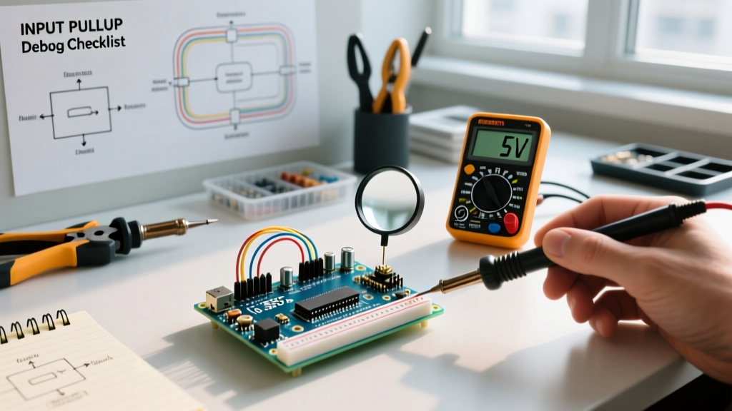
Before finalizing your next Arduino schematic, run your input design through this optimization checklist:
- BOM Reduction: Are you using
INPUT_PULLUPto eliminate external 10kΩ resistors? - Logic Verification: Does your code expect
LOWwhen the button is actuated? - Pin Safety: Have you verified that your chosen GPIOs are not reserved for boot strapping (especially on ESP32)?
- Debounce Strategy: Is the Bounce2 library implemented for software filtering, or is an RC/Schmitt network present for high-EMI environments?
- Interconnects: Have Dupont wires been replaced with locking JST-XH or PicoBlade connectors for enclosure integration?
By treating button inputs not as an afterthought, but as a critical subsystem requiring deliberate architectural choices, you elevate your Arduino projects from fragile prototypes to robust, deployable hardware.