
Why Migrate Your Arduino Radio Control Setup?
For over a decade, the 433MHz ASK/OOK (Amplitude Shift Keying) transmitter and receiver pairs have been the default entry point for arduino radio control projects. Modules like the FS1000A transmitter and XY-MK-5V receiver are incredibly cheap and easy to wire. However, as maker projects evolve into complex outdoor robotics, agricultural telemetry, and long-range RC vehicles, the limitations of legacy ASK modulation become glaringly obvious. Susceptibility to noise, poor multipath fading resistance, and a hard range ceiling of about 100 meters (line-of-sight) severely bottleneck advanced builds.
As of 2026, the industry standard for low-power, long-range maker communications is LoRa (Long Range), utilizing Chirp Spread Spectrum (CSS) modulation. Migrating your arduino radio control setup from 433MHz ASK to an 868/915MHz LoRa architecture fundamentally transforms your project's capabilities, boosting range from mere meters to several kilometers while maintaining a low power footprint. This guide provides a comprehensive, component-level migration path for upgrading your hardware, wiring, and software.
Hardware Comparison: Legacy ASK/OOK vs. Modern LoRa
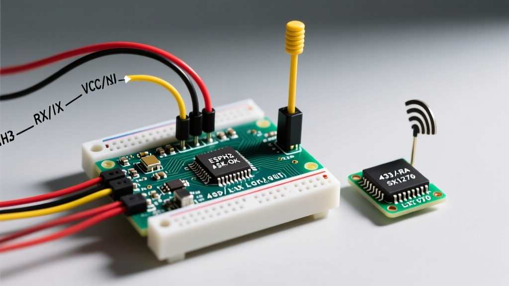
Before ripping out your existing RF modules, it is crucial to understand the electrical and physical differences between the legacy 433MHz ecosystem and modern SX126x-based LoRa modules. The table below contrasts the ubiquitous FS1000A/XY-MK-5V pairing with a modern 2026 maker favorite, the Heltec HT-RA62 (based on the Semtech SX1262 chip).
| Specification | Legacy 433MHz (FS1000A / XY-MK-5V) | Modern LoRa (Heltec HT-RA62 / SX1262) |
|---|---|---|
| Modulation | ASK / OOK | Chirp Spread Spectrum (CSS) |
| Typical Range (LOS) | 30m – 100m | 5km – 15km |
| TX Current Draw | ~15 mA | ~115 mA (at +22dBm) |
| RX Current Draw | ~4 mA | ~5.2 mA |
| MCU Interface | Single GPIO Pin | Hardware SPI + GPIO (CS, RST, DIO) |
| Operating Voltage | 3.3V – 5V (TX up to 12V for range) | Strictly 1.8V – 3.7V |
| Avg. Module Cost (2026) | $1.50 (pair) | $5.50 – $7.00 (each) |
While the LoRa modules are roughly four times more expensive per node, the cost-per-kilometer of range is exponentially lower. Furthermore, the SX1262 architecture resolves the high standby current issues of the older SX1278 chips, making it vastly superior for battery-operated RC nodes.
Wiring Migration: From Single-Pin to Hardware SPI
The most jarring change when upgrading your arduino radio control system is the wiring complexity. Legacy 433MHz modules require only a single digital pin for data. LoRa modules, however, require a full hardware SPI bus plus dedicated control pins.
Standard Arduino Uno / Nano SPI Pinout Mapping
- MOSI: Pin 11
- MISO: Pin 12
- SCK: Pin 13
- CS (Chip Select): Pin 10 (Configurable)
- RST (Reset): Pin 9 (Configurable)
- DIO1 (Interrupt): Pin 2 (Must be interrupt-capable)
According to the official Arduino SPI documentation, utilizing the hardware SPI bus is mandatory for LoRa modules to ensure the microcontroller can push configuration registers fast enough before the RF transmission window closes. Software SPI (bit-banging) is highly discouraged for SX126x modules due to strict timing requirements.
CRITICAL VOLTAGE WARNING: Almost all 5V Arduino boards (Uno, Nano, Mega) will instantly destroy a 3.3V LoRa module's SPI pins if connected directly. You must use a logic level shifter (such as a TXS0108E or CD4050B) for the MOSI, SCK, CS, and RST lines, or migrate your project to a native 3.3V microcontroller like the Arduino Nano 33 IoT or an ESP32-S3.
Power Delivery and Decoupling Upgrades
A common failure mode during arduino radio control migrations is brownout resetting the MCU during a LoRa transmission. When an SX1262 module transmits at +22dBm, it draws a transient spike of roughly 115mA to 120mA. The onboard 3.3V LDO regulators found on cheap breadboard power supplies or the Arduino's internal 3.3V regulator often cannot supply this transient current, leading to voltage droop and SPI bus corruption.
The 470µF Decoupling Rule
To stabilize the power rail during RF bursts, you must solder a 470µF low-ESR electrolytic capacitor and a 100nF ceramic capacitor in parallel directly across the VCC and GND pins of the LoRa module. This localized energy reservoir handles the microsecond current spikes that the main board's voltage regulator cannot react to fast enough.
Software Migration: Moving to RadioLib
Legacy 433MHz sketches typically rely on the deprecated VirtualWire library or the RH_ASK driver from the RadioHead suite. For modern LoRa implementations, the undisputed standard in 2026 is the RadioLib GitHub repository, maintained by Jan Gromeš. It provides robust, non-blocking APIs for virtually every digital radio module on the market.
Translating Your Payload Structure
ASK modules blindly push raw bytes. LoRa operates on structured packets with headers, sync words, and CRC (Cyclic Redundancy Check) validation. Below is a minimal migration example showing how to initialize an SX1262 module and transmit a basic RC telemetry string.
#include <RadioLib.h>

// SX1262 pinout: CS=10, DIO1=2, NRST=9, BUSY=3
SX1262 radio = new Module(10, 2, 9, 3);

void setup() {
  Serial.begin(115200);
  // Initialize at 915.0 MHz, BW 125kHz, SF 7, CR 5
  int state = radio.begin(915.0, 125.0, 7, 5, 0x18, 22, 8, 1.6, false);
  if (state == RADIOLIB_ERR_NONE) {
    Serial.println(F("LoRa Module Initialized."));
  } else {
    Serial.print(F("Failed, code ")); Serial.println(state);
    while (true);
  }
}

void loop() {
  String rcTelemetry = "THR:1500,STR:1600,ALT:45.2";
  Serial.print(F("Transmitting... "));
  int state = radio.transmit(rcTelemetry);
  if (state == RADIOLIB_ERR_NONE) {
    Serial.println(F("Success!"));
  }
  delay(100);
}
Notice the explicit definition of Spreading Factor (SF 7) and Bandwidth (125kHz). For high-speed RC control links where latency is more critical than extreme range, keeping the SF at 7 or 8 is vital. Higher spreading factors (SF 11 or 12) drastically increase time-on-air, introducing latency that can cause RC vehicles to become unresponsive.
Real-World Edge Cases and RF Troubleshooting
Upgrading your hardware is only half the battle. RF physics dictate that your arduino radio control migration will encounter real-world edge cases that don't exist in simulated IDE environments.
Antenna VSWR and Impedance Matching
Legacy 433MHz kits often include a 17.3cm straight wire antenna. If you upgrade to a 915MHz LoRa module, using that same wire will result in a massive Voltage Standing Wave Ratio (VSWR) mismatch, reflecting power back into the SX1262's PA (Power Amplifier) and potentially burning it out. You must use a properly tuned 915MHz SMA antenna or a 8.2cm copper wire for 915MHz (8.6cm for 868MHz EU bands). As noted in Semtech's official LoRa primer, proper antenna matching is the single highest-impact factor on link budget.
SPI Bus Capacitance on Long Runs
In large RC boats or agricultural rovers, you might need to run wires from the MCU to the LoRa module over distances greater than 15cm. Long breadboard jumper wires introduce parasitic capacitance on the SPI lines, causing the high-frequency clock edges to round off. This leads to RADIOLIB_ERR_SPI_WRITE_FAILED errors. The fix: Drop the SPI clock speed in your initialization code, or use shielded ribbon cable with a grounded drain wire for SPI runs exceeding 20cm.
Summary of the Migration Path
Migrating your arduino radio control infrastructure from 433MHz ASK to LoRa is a transformative upgrade. By addressing the SPI wiring requirements, implementing proper 3.3V logic shifting, stabilizing the power rail with low-ESR capacitors, and adopting the RadioLib software stack, you will unlock kilometers of reliable, noise-immune range. While the initial hardware cost and wiring complexity are higher, the resulting telemetry and control reliability are indispensable for professional-grade maker projects in 2026 and beyond.