
The Core Compatibility Problem: AVR vs. VGA Timings
Connecting a standard Arduino to a VGA monitor is one of the most requested but fundamentally misunderstood projects in the maker community. When you search for an arduino to vga monitor solution, you are immediately confronted with a harsh hardware reality: the classic Arduino Uno or Nano (based on the ATmega328P) lacks the memory and clock speed to natively drive a standard 640x480 VGA signal.
A standard 640x480 VGA display at 60Hz requires a pixel clock of 25.175 MHz and precise horizontal and vertical sync pulses. The ATmega328P runs at 16 MHz and possesses a mere 2KB of SRAM. A single 640x480 frame buffer at just 1-bit color depth requires 38,400 bytes (37.5KB) of RAM—nearly 20 times more memory than the chip physically contains. Furthermore, bit-banging a 25MHz signal on a 16MHz AVR results in severe timing jitter, which modern LCD monitors with strict scaler boards will outright reject, displaying an "Out of Range" or "No Signal" error.
However, bridging an Arduino to a VGA monitor is entirely possible if you choose the right compatibility path. This guide breaks down the legacy AVR hacks and the modern ESP32-based solutions that serve as the 2026 standard for microcontroller video output.
Method 1: Arduino Uno (ATmega328P) via Bit-Banging
If you are strictly limited to an Arduino Uno or Nano, you cannot achieve standard 640x480 resolution. Instead, you must rely on aggressive software optimization and reduced resolutions. The most reliable library for this is VGAx, developed by Sandro Maffiodo. VGAx generates a 160x120 pixel resolution with 1-bit color (black and white) or a heavily restricted 128x96 4-color palette.
The Resistor DAC Setup
To output analog RGB signals from digital Arduino pins, you must build a simple Digital-to-Analog Converter (DAC) using a resistor ladder. For a basic 8-color output (3-bit RGB), you wire three digital pins directly to the Red, Green, and Blue VGA pins. For higher color depth, an R-2R resistor ladder is required, though the Uno's limited I/O pins make this impractical for anything beyond 6-bit color.
- Resolution: 160x120 (Monochrome) or 128x96 (4-Color)
- Frame Rate: ~60Hz (highly dependent on CPU load)
- RAM Usage: ~2.4KB (leaves almost no room for complex sketch logic)
- Cost: ~$15 for an Uno clone + $2 for resistors
Expert Warning: Modern LCD monitors manufactured after 2018 feature highly sensitive timing controllers. The slight sync jitter inherent in AVR bit-banging often causes modern Dell, LG, and Samsung monitors to drop the signal entirely. For Method 1, you will have the highest success rate using older CRT monitors or LCDs with tolerant, generic scaler boards.
Method 2: The 2026 Standard (ESP32 & FabGL Library)
To achieve true, flicker-free VGA output at 640x480 or even 800x600, the maker community has universally shifted to the ESP32 ecosystem. Specifically, the ESP32-S3 with 8MB of Octal PSRAM is the current gold standard. The ESP32 features dedicated I2S and LCD camera peripherals that can be reverse-engineered to output parallel RGB data with hardware-level timing precision, completely eliminating the jitter that plagues the Arduino Uno.
The definitive software solution is the FabGL library by Fabrizio Di Vittorio. FabGL handles the complex DMA (Direct Memory Access) buffering, freeing the main CPU cores to handle your application logic while the hardware peripherals push pixels to the VGA monitor flawlessly.
VGA Signal Voltage Math
The VGA standard (VESA) dictates that analog RGB signals must have a peak-to-peak voltage of 0.7V into a 75-ohm load. The ESP32 operates at 3.3V logic. If you connect a 3.3V GPIO pin directly to a VGA monitor, you risk damaging the monitor's internal ADC or washing out the colors entirely. You must drop the voltage using a series resistor.
Using the voltage divider formula: V_out = V_in * (R_load / (R_series + R_load))
If we use a standard 270-ohm series resistor and the monitor provides the 75-ohm pull-down termination:
V_out = 3.3V * (75 / (270 + 75)) = 3.3V * (75 / 345) = 0.717V
This 0.717V output is virtually perfect for the 0.7V VESA specification, ensuring crisp, accurate colors without requiring active level-shifting ICs.
Microcontroller VGA Compatibility Matrix
| Microcontroller | Max Resolution | Color Depth | Timing Stability | Library / Ecosystem | Approx. Cost (2026) |
|---|---|---|---|---|---|
| Arduino Uno (ATmega328P) | 160x120 | 1-bit to 4-color | Poor (High Jitter) | VGAx | $12 - $18 |
| Teensy 4.1 (i.MX RT1062) | 800x600 | 8-bit to 16-bit | Excellent | Teensyduino / Custom | $38 - $45 |
| ESP32 (Classic DevKit V1) | 640x480 | 8-bit (64 colors) | Excellent | FabGL | $6 - $9 |
| ESP32-S3 (WROOM-1, 8MB PSRAM) | 800x600 / 1024x768 | 16-bit (65k colors) | Excellent | FabGL / ESP-LCD | $8 - $12 |
Step-by-Step Wiring: ESP32 to VGA DE-15 Connector
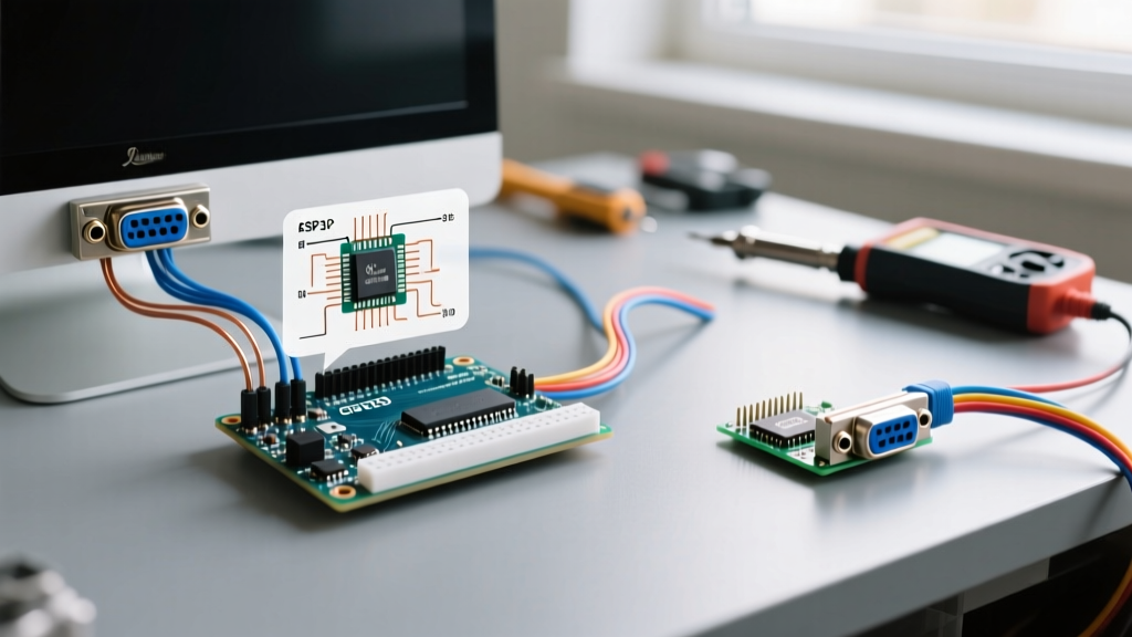
Below is the standard wiring configuration for driving a VGA monitor using a classic ESP32 DevKit V1 and the FabGL library. You will need a female DE-15 VGA breakout board or a salvaged VGA cable, and fourteen 270-ohm resistors.
- Red Channel (3-bit): Connect ESP32 GPIO 22, 21, and 27 to VGA Pin 1 (Red) through three separate 270-ohm resistors. Join the resistor outputs at the VGA pin.
- Green Channel (3-bit): Connect ESP32 GPIO 19, 18, and 5 to VGA Pin 2 (Green) through 270-ohm resistors.
- Blue Channel (2-bit): Connect ESP32 GPIO 4 and 2 to VGA Pin 3 (Blue) through 270-ohm resistors.
- Horizontal Sync (H-Sync): Connect ESP32 GPIO 23 to VGA Pin 13. (No resistor needed; 3.3V TTL logic is accepted by modern VGA sync inputs, though a 100-ohm series resistor can prevent ringing).
- Vertical Sync (V-Sync): Connect ESP32 GPIO 15 to VGA Pin 14.
- Grounding: Connect the ESP32 GND to VGA Pins 5, 6, 7, 8, and 10. Do not skip the multiple ground pins; VGA relies on separate analog and digital ground returns to prevent color bleeding and ghosting.
Troubleshooting Edge Cases & Sync Failures
Even with perfect wiring, connecting a microcontroller to a VGA display can yield frustrating edge cases. Here is how to diagnose the most common failures based on standard VESA timing parameters.
1. The "Signal Out of Range" Error
Cause: The monitor's scaler chip detects an H-Sync or V-Sync frequency outside its supported EDID profile. This happens if your FabGL configuration defaults to a 72Hz or 75Hz refresh rate, but the monitor only accepts 60Hz.
Fix: In your FabGL initialization code, explicitly force the 640x480 @ 60Hz resolution. Ensure your V-Sync pulse width is exactly 2 lines (63.5 microseconds) and the back porch is correctly allocated.
2. Image Tearing or Rolling Vertically
Cause: V-Sync polarity inversion. The VGA standard dictates that V-Sync should be negative polarity (active low) for 640x480. If your microcontroller is driving it active high, the monitor will fail to lock onto the frame boundary.
Fix: Check your library configuration. In FabGL, ensure the sync polarity flags are set to HSYNC_POSITIVE and VSYNC_NEGATIVE for standard 480p modes.
3. Color Banding or Dim Output
Cause: Ground loop interference or incorrect resistor values. If you used 330-ohm or 470-ohm resistors instead of 270-ohm, the voltage will drop below the 0.7V threshold, resulting in a dim, washed-out image. Additionally, failing to tie the ESP32 ground to the VGA analog ground (Pins 6, 7, 8) will introduce digital noise into the analog RGB lines.
Fix: Verify resistor values with a multimeter. Ensure all five VGA ground pins are bridged to the ESP32 ground plane. For high-frequency noise, adding a small 100pF ceramic capacitor between each RGB line and ground can act as a low-pass filter, smoothing out the digital staircase waveform into a cleaner analog signal.
Final Verdict
While searching for an "arduino to vga monitor" tutorial often leads to legacy ATmega328P bit-banging guides, the practical reality of modern hardware dictates a different approach. If your project requires basic, low-resolution telemetry or retro game rendering on a forgiving CRT screen, the Arduino Uno with VGAx is a fun, educational exercise in CPU cycle counting. However, for any serious 2026 application requiring stable 640x480 output, terminal emulation, or complex GUIs, migrating to an ESP32-S3 utilizing the FabGL library is the only reliable, production-ready compatibility path.