
Quick Reference: Selecting the Right Potentiometer for MCU Projects
When integrating Arduino potentiometers into your microcontroller projects, selecting the correct resistive element material is just as critical as choosing the right resistance value. The physical construction of the potentiometer dictates its lifespan, noise profile, and rotational smoothness. Below is a quick-reference matrix for the three most common potentiometer materials used in maker and industrial electronics.
| Material Type | Common Model Examples | Rotational Lifespan | Avg. Cost (2026) | Best MCU Application |
|---|---|---|---|---|
| Carbon Composition | Generic 10kΩ breadboard pots | 10,000 - 15,000 cycles | $0.10 - $0.50 | Prototyping, basic user inputs, low-budget educational kits. |
| Cermet (Ceramic/Metal) | Bourns 3386 Series (Trimpots) | 200+ cycles (Trimmers) 1,000,000+ (Panel) |
$0.80 - $2.50 | Calibration dials, set-and-forget trimmers, high-temperature environments. |
| Conductive Plastic | Alps RK27, Bourns PTD90 | 1,000,000+ cycles | $3.00 - $12.00 | High-resolution MIDI controllers, precision robotics, audio mixing surfaces. |
Core Wiring & Configuration FAQ
How exactly do I wire a 3-pin potentiometer to an Arduino?
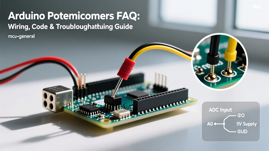
A standard 3-pin potentiometer acts as a variable voltage divider. To interface it with an Arduino Uno (ATmega328P) or similar 5V board, use the following wiring scheme:
- Pin 1 (Left): Connect to 5V (VCC).
- Pin 2 (Center/Wiper): Connect to an Analog Input pin (e.g., A0).
- Pin 3 (Right): Connect to GND.
Pro-Tip: If you accidentally swap the 5V and GND connections on the outer pins, you will not damage the microcontroller. However, rotating the shaft clockwise will decrease the analog value (1023 down to 0) instead of increasing it. You can fix this in software by inverting the reading: int val = 1023 - analogRead(A0);
Do I need a pull-down or pull-up resistor when using a potentiometer?
No. Unlike mechanical switches or pushbuttons that leave a pin floating when open, a potentiometer's wiper is always physically connected to a specific point on the resistive track. It continuously provides a definitive voltage between 0V and VCC, meaning internal or external pull-up/pull-down resistors are entirely unnecessary and will actually introduce voltage reading errors.
Advanced ADC & Jitter Troubleshooting
Why is my analogRead() value jittering or fluctuating?
Jitter is the most common issue when working with Arduino potentiometers. If your serial monitor shows values bouncing between 510 and 514 while the shaft is perfectly still, you are likely experiencing one of two issues: ADC impedance mismatch or mechanical track noise.
The 10kΩ Impedance Rule: According to the official Arduino analogRead() documentation and the underlying ATmega328P datasheet, the analog-to-digital converter (ADC) utilizes a sample-and-hold (S/H) capacitor (approx. 14pF). This capacitor must charge to the input voltage level within a fraction of a microsecond. If your potentiometer's total resistance is too high (e.g., 100kΩ or 1MΩ), the source impedance exceeds the recommended 10kΩ maximum. The S/H capacitor cannot charge fully before the ADC samples it, resulting in random, low-value jitter.
The Fix: Stick to 10kΩ or 50kΩ potentiometers for 5V Arduinos. If you must use a high-resistance pot, solder a 0.1µF ceramic capacitor between the wiper pin and GND to act as a hardware low-pass filter.
How does the ESP32 handle potentiometers differently?
If you have migrated from the Arduino Uno to the ESP32, you will notice that ESP32 ADC pins (GPIO 32-39) are notoriously non-linear and highly sensitive to impedance. For ESP32 projects:
- Use a 10kΩ linear potentiometer. Higher values will cause massive jitter due to the ESP32's internal ADC architecture.
- The ESP32 ADC is 12-bit (0-4095) but saturates around 3.1V to 3.3V depending on the specific silicon batch and attenuation settings.
- Always use the
analogReadMilliVolts()function in the ESP32 Arduino core rather than rawanalogRead(), as it utilizes the chip's factory-calibrated eFuse data to provide a much more accurate linear mapping.
Taper & Mapping Quick Reference
Linear (B-Taper) vs. Logarithmic (A-Taper): Which should I use?
Potentiometers are manufactured with different resistance curves, known as tapers. Understanding the difference is vital for predictable MCU mapping.
| Taper Type | Marking Code | Behavior | When to Use with Arduino |
|---|---|---|---|
| Linear | B (e.g., B10K) | Resistance changes at a constant rate relative to shaft rotation. | Position sensing, motor speed control, LED dimming, UI menus. |
| Logarithmic (Audio) | A (e.g., A10K) | Resistance changes slowly at first, then exponentially. Matches human hearing perception. | Audio volume control via digital potentiometers or DACs. Avoid for physical position tracking. |
| Reverse Log | C (e.g., C10K) | Opposite of Logarithmic. Rapid initial change, then flattens out. | Specialized sensor calibration, specific lighting curves. |
For 95% of maker projects involving servos, motors, and screen scrolling, you must purchase Linear (B-Taper) potentiometers. Using an Audio taper for a servo arm will result in the servo moving very slowly for the first half of the dial's rotation, then snapping rapidly to the end position.
Software Quick Reference: Smoothing Jittery Inputs
Even with a perfect 10kΩ cermet potentiometer, environmental electrical noise can cause minor ADC fluctuations. Instead of relying on the standard map() function which will amplify this jitter, implement an Exponential Moving Average (EMA) filter in your Arduino sketch.
The EMA algorithm requires minimal memory (only one float variable) and provides buttery-smooth input readings without the lag associated with taking an average of 50 historical samples.
// EMA Filter Quick Reference
float smoothedValue = 0;
const float alpha = 0.05; // Lower = smoother but more lag (0.01 to 0.1)

void loop() {
  int rawInput = analogRead(A0);
  smoothedValue = (alpha * rawInput) + ((1 - alpha) * smoothedValue);

  // Use smoothedValue for your servos or PWM outputs
  int pwmOut = map((int)smoothedValue, 0, 1023, 0, 255);
  analogWrite(9, pwmOut);
}
Troubleshooting Matrix: Common Potentiometer Failures
Use this diagnostic matrix to quickly isolate hardware and software faults in your Arduino potentiometer circuits.
| Symptom | Probable Root Cause | Hardware / Software Fix |
|---|---|---|
| Value sticks at 1023 regardless of rotation. | Wiper pin is shorted to VCC, or GND wire is disconnected. | Check continuity from Pin 3 to GND with a multimeter. Reseat breadboard wires. |
| Value reads 0, then suddenly jumps to random numbers. | Carbon track is worn out or physically scratched inside the housing. | Replace the potentiometer. Consider upgrading to a Bourns conductive plastic model. |
| Servo twitches violently when pot is moved. | Power supply brownout. The servo is drawing current from the Arduino's 5V rail, causing the analog reference voltage to sag. | Power the servo from an external 5V/2A buck converter. Tie the external GND to the Arduino GND. |
| Readings are accurate, but mapping feels 'backwards'. | VCC and GND are swapped on the outer lugs. | Swap the outer wires, or apply val = 1023 - analogRead(A0); in code. |
| ESP32 reading maxes out at ~2800 instead of 4095. | ESP32 ADC non-linearity and saturation above 3.1V. | Use a voltage divider to drop the 3.3V max down to 2.5V, or use analogSetAttenuation(ADC_11db). |
Further Reading & Authoritative Sources
To dive deeper into the physics of variable resistors and microcontroller analog-to-digital conversion, consult the following resources:
- Arduino Language Reference: analogRead() - Official documentation detailing ADC resolution, pin mappings across different Arduino architectures, and timing constraints.
- All About Circuits: Potentiometers and Rheostats - An excellent primer on the internal mechanical differences between potentiometers used as voltage dividers versus rheostats used as variable current limiters.