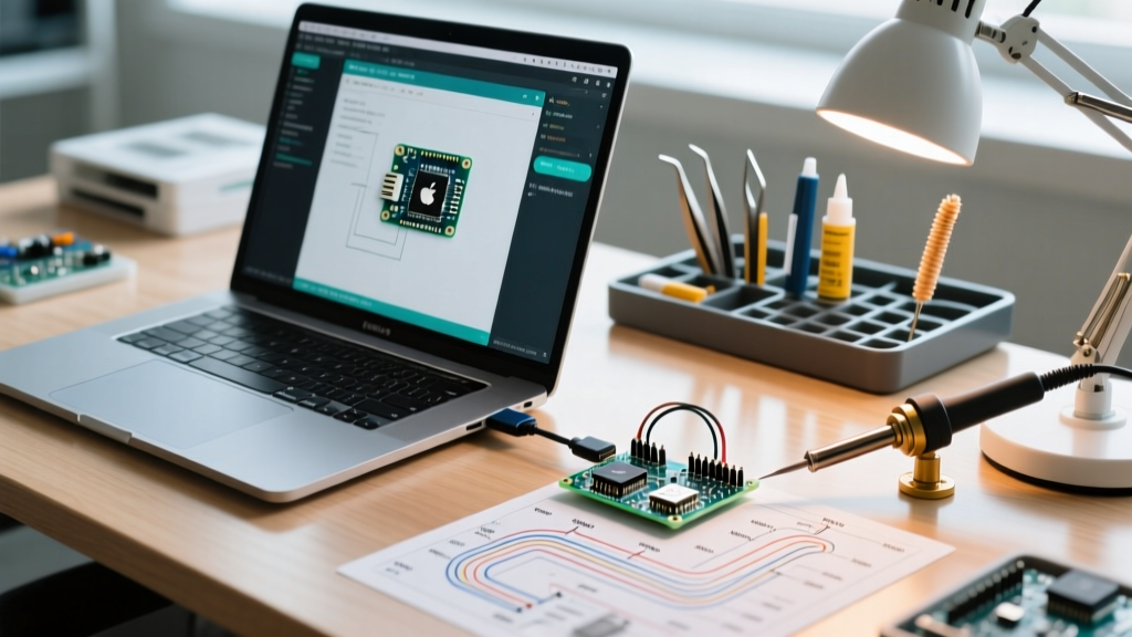

Building autonomous machines is one of the most rewarding applications for microcontrollers, but the transition from a blinking LED to a fully functional autonomous rover often exposes severe developmental bottlenecks. When utilizing Arduino in robotics, the primary challenge is rarely the lack of hardware capability; rather, it is the lack of a structured, optimized workflow. Hobbyists and engineers alike frequently fall into the trap of 'spaghetti wiring' and blocking code, leading to endless debugging sessions and fragile prototypes.
To build robust robotic systems in 2026, makers must adopt professional engineering workflows tailored for the Arduino ecosystem. This guide explores how to optimize your hardware design, firmware architecture, and testing pipelines to drastically reduce iteration time and eliminate common failure modes.
The Hidden Cost of Spaghetti Wiring and Blocking Code
The most common point of failure in early-stage robotics projects is physical. Solderless breadboards and Dupont jumper wires are excellent for testing a single I2C sensor on a desk, but they are catastrophic in a mobile robotic platform. The vibration from DC gear motors, servos, and chassis movement causes micro-disconnects. A momentary loss of ground on an I2C bus can lock up the ATmega328P or RP2040, requiring a hard power cycle.
Similarly, relying on the delay() function in your firmware creates a 'blind' robot. If your ultrasonic sensor polling loop includes a 500-millisecond delay to wait for a motor to settle, your robot is entirely blind to dynamic obstacles for half a second. At a modest speed of 1 meter per second, your robot will travel half a meter before it can react to a sudden drop-off or collision.
Hardware Workflow: Escaping the Dupont Wire Trap
Optimizing your hardware workflow means moving away from temporary connections as early as possible without sacrificing the ability to iterate. You do not need to jump straight to a 4-layer custom PCB. Instead, implement a phased hardware workflow.
Phase 1: Screw-Terminal Proto Shields
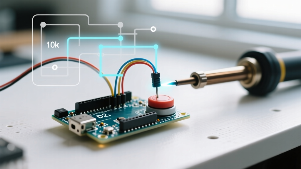
Before designing a custom PCB, transition your validated breadboard circuit to an Arduino Proto Shield with screw terminals. This eliminates vibration-induced disconnects. For approximately $18, an official Arduino Proto Shield Rev3 provides a robust foundation. Solder your critical connections, such as motor driver logic pins and I2C pull-up resistors, directly to the prototyping area.
Phase 2: Component Selection and KiCad Integration
When you are ready to design a custom motor shield using KiCad 8 or Altium, optimize your component selection for modern robotics. Many beginners default to the L298N motor driver because it is ubiquitous in starter kits. However, the L298N is a BJT-based H-bridge with a massive voltage drop (often 2V to 3V) and poor thermal efficiency.
- Legacy Choice: L298N Module (~$8.00). Heavy, requires massive heatsinks, wastes battery capacity as heat.
Firmware Optimization: State Machines Over Blocking Delays
A professional robotics firmware workflow abandons linear, blocking scripts in favor of non-blocking, event-driven architectures. The Arduino BlinkWithoutDelay documentation is the foundational text for this concept, utilizing the
millis()function to track time without halting the CPU.For complex robots, managing multiple
millis()timers manually becomes unwieldy. Optimize your workflow by integrating a cooperative multitasking library likeTaskScheduleror a lightweight Finite State Machine (FSM) library a dedicated sensor task, a navigation task, and a telemetry task.- Modularity: Tasks can be enabled, disabled, or delayed dynamically based on the robot's current state (e.g., disabling the mapping task while the robot is executing an emergency stop).
Workflow Tip: Never read I2C sensors inside your main motor control loop. I2C transactions can stretch if the bus is noisy or the sensor is busy. Offload sensor reading to a dedicated, lower-priority task that updates a global struct, and have your motor control loop simply read the latest cached values.
Simulation and Automated Testing Pipelines
Hardware iteration is slow and expensive. You can optimize your development cycle by shifting logic validation to the simulation and CI/CD (Continuous Integration/Continuous Deployment) phase before flashing a physical board.
Logic Validation with Wokwi
Wokwi has become an indispensable tool for Arduino robotics. You can simulate complex I2C sensors, OLED displays, and motor logic in the browser. If you are writing a PID controller for a self-balancing robot, you can simulate the IMU data feed and tune your PID constants in Wokwi before ever powering up the physical motors, saving hours of hardware debugging and potential component damage.
Automated Builds with PlatformIO
The Arduino IDE is excellent for beginners, but it lacks the dependency management and build automation required for serious robotics projects. Migrating to PlatformIO within VS Code allows you to manage libraries via a platformio.ini file. By integrating PlatformIO with GitHub Actions, you can leverage the PlatformIO Continuous Integration guide to automatically compile your firmware and run unit tests every time you push code. This ensures that a new navigation feature doesn't accidentally break your motor driver logic.
Summary: The Optimized Robotics Workflow
Transitioning from a hobbyist mindset to an optimized engineering workflow transforms how you approach Arduino in robotics. By prioritizing robust power architectures, non-blocking firmware design, and virtual simulation, you spend less time chasing phantom electrical bugs and more time refining your robot's autonomous behavior.