
The Evolution of Arduino Sonic Sensor Integration
When makers and engineers refer to an 'arduino sonic' setup, they are almost exclusively talking about ultrasonic distance measurement modules. These sensors emit high-frequency acoustic pulses (typically 40 kHz) and measure the time-of-flight (ToF) of the echo to calculate distance. While the hobbyist community has relied on 5V logic for over a decade, the modern microcontroller landscape has shifted dramatically. Today's premier development boards, including the Arduino Nano 33 IoT, Nano 33 BLE, and Portenta H7, operate on 3.3V logic. This architectural shift has created a massive compatibility gap for legacy 5V sonic sensors.
In this comprehensive compatibility guide, we will dissect the electrical and logical requirements of the most popular sonic sensors on the market. We will explore exact wiring topologies, logic-level translation circuits, and environmental edge cases to ensure your ultrasonic projects function flawlessly in 2026 and beyond.
Critical Warning: Never connect a 5V Echo pin directly to a 3.3V Arduino GPIO. While a single accidental connection might not instantly destroy an ARM Cortex-M4 microcontroller, repeated exposure to 5V logic will degrade the internal ESD protection diodes, leading to phantom reads, increased leakage current, and eventual silicon failure.
Core Sonic Sensor Models Compared
Before addressing logic-level compatibility, we must establish the baseline specifications of the three dominant sonic sensors used in Arduino ecosystems. Pricing and availability reflect the current 2026 market landscape.
| Sensor Model | Native Voltage | Interface | Max Range | Beam Angle | Est. Price (2026) |
|---|---|---|---|---|---|
| HC-SR04 | 5.0V DC | Digital Trigger/Echo | 400 cm | ~15° | $1.50 - $2.50 |
| JSN-SR04T (V2.0) | 5.0V DC | Digital Trigger/Echo | 450 cm | ~20° | $7.00 - $9.50 |
| MaxBotix MB1010 (LV-MaxSonar-EZ1) | 2.5V - 5.5V | Analog, PWM, Serial | 645 cm | ~42° | $28.00 - $32.00 |
The 5V vs 3.3V Logic Level Crisis
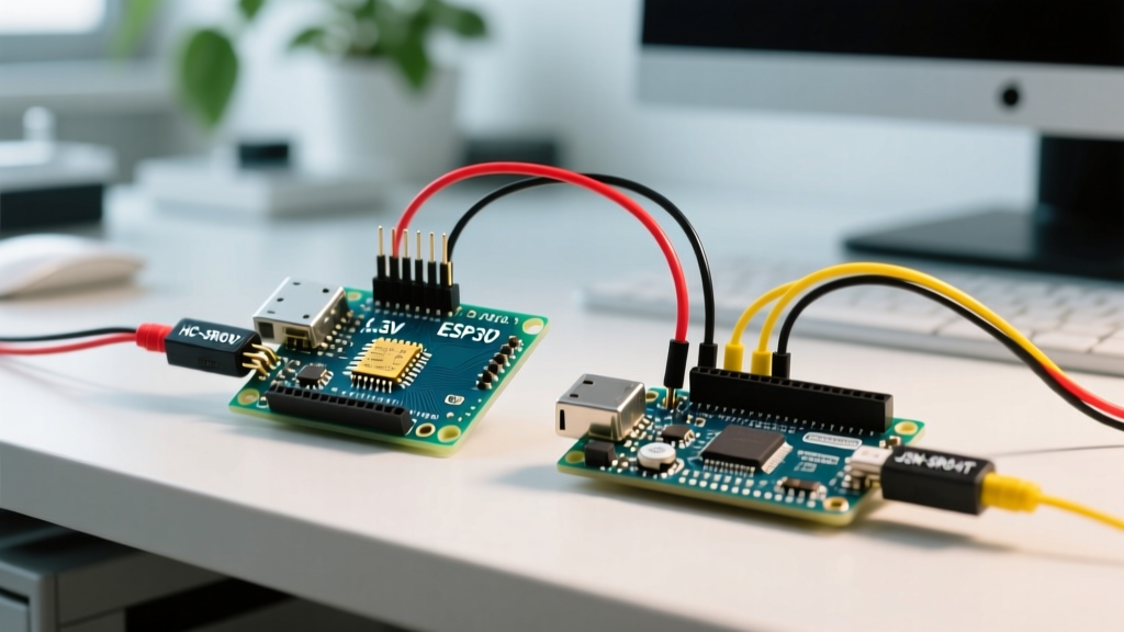
The HC-SR04 and its waterproof sibling, the JSN-SR04T, are natively 5V devices. When integrating these with 3.3V Arduinos, you face a bidirectional logic mismatch that requires two distinct hardware interventions.
1. The Echo Pin (5V Output to 3.3V Input)
The sonic sensor outputs a 5V HIGH signal on the Echo pin for the duration of the sound wave's flight. To safely read this on a 3.3V Arduino, you must step down the voltage. The most cost-effective method is a passive resistor voltage divider. According to the SparkFun Voltage Divider Tutorial, using a 1kΩ resistor in series (R1) and a 2kΩ resistor to ground (R2) will yield exactly 3.33V from a 5V source.
- Wiring: Echo Pin -> 1kΩ Resistor -> Arduino GPIO -> 2kΩ Resistor -> GND.
- Edge Case: At high ping rates (e.g., >30 Hz), the RC time constant created by the GPIO's parasitic capacitance and the divider resistors can round off the sharp edges of the pulse, causing microsecond-level timing inaccuracies. If you require sub-millimeter precision, use a BSS138 MOSFET-based bidirectional logic level converter instead.
2. The Trigger Pin (3.3V Output to 5V Input)
This is the most commonly overlooked failure point in arduino sonic projects. The HC-SR04 requires a minimum 10-microsecond HIGH pulse on the Trigger pin to initiate a measurement. While the datasheet claims a 2.0V threshold for a logical HIGH, cheap cloned HC-SR04 modules often feature degraded silicon that fails to register a 3.3V trigger pulse reliably. This results in the sensor returning a flat '0 cm' or timing out entirely.
The Fix: If your 3.3V Arduino fails to trigger the sensor, you must shift the trigger signal up to 5V. A simple NPN transistor (like the 2N3904) or a dedicated logic level shifter IC (like the 74LVC245) will guarantee a robust 5V trigger pulse. For quick prototyping, powering the HC-SR04 VCC pin with 3.3V *sometimes* works, but it severely reduces the acoustic output power, cutting your maximum reliable range from 4 meters down to roughly 1.5 meters.
MaxBotix LV-MaxSonar: The Native 3.3V Alternative
If you are designing a professional product or a high-reliability IoT node using the Arduino Portenta H7 or Nano 33 BLE, bypass the HC-SR04 entirely. The MaxBotix LV-MaxSonar series (the 'LV' denotes Low Voltage) is engineered to operate natively from 2.5V to 5.5V.
When powered directly from the 3.3V output pin of a modern Arduino, the MB1010 eliminates the need for logic shifters. However, you must adjust your data parsing strategy based on the interface you choose:
- Analog Voltage: The analog output scales proportionally with VCC. At 3.3V, the scaling factor is approximately 6.4mV per inch. You must use the Arduino's internal 3.3V reference for the ADC to maintain accuracy.
- Pulse Width (PWM): This is the recommended interface for 3.3V boards. The sensor outputs a HIGH pulse where the width represents the distance (147µs per inch). This timing is independent of VCC, meaning your
pulseIn()code requires zero modifications regardless of whether you power the sensor at 3.3V or 5V. - Serial (RS232 Format): The serial output is inverted. You will need to use the Arduino
SoftwareSeriallibrary with theinvertedflag set to true, or wire it through a hardware inverter.
Environmental Edge Cases: Temperature and Acoustic Crosstalk
Sonic sensors do not measure distance directly; they measure time. The microcontroller calculates distance by assuming a fixed speed of sound (typically 343 meters per second). However, the speed of sound in air is highly dependent on temperature and humidity.
Implementing Real-Time Temperature Compensation
The formula for the speed of sound in dry air is v = 331.3 + (0.606 × T), where T is the temperature in Celsius. If your Arduino sonic project operates in an unheated warehouse (e.g., 5°C) versus a hot greenhouse (e.g., 35°C), the speed of sound varies from 334 m/s to 352 m/s. This introduces a 5.4% error margin—translating to a 5.4 cm error on a 1-meter measurement.
Actionable Fix: Integrate an AHT20 or DS18B20 temperature sensor into your circuit. Read the ambient temperature before firing the sonic pulse, and dynamically update the divisor in your C++ code:
float tempC = sensors.getTempCByIndex(0);
float speedOfSound = 331.3 + (0.606 * tempC); // meters per second
float distanceCm = (durationMicros / 2.0) * (speedOfSound / 10000.0);
Multi-Sensor Acoustic Crosstalk
When deploying multiple sonic sensors on a single robot or tank level monitor, acoustic crosstalk occurs when Sensor A reads the echo generated by Sensor B. To resolve this, you must implement a sequential firing array. According to Arduino Official Documentation best practices for timing, you should never poll multiple ultrasonic sensors simultaneously. Instead, trigger Sensor 1, wait for the echo to timeout (approx. 25ms for 4 meters), add a 50ms acoustic dampening delay, and then trigger Sensor 2.
Frequently Asked Questions (FAQ)
Can I use the NewPing library with 3.3V Arduinos?
Yes, the NewPing library is highly recommended for 3.3V ARM-based Arduinos. It utilizes hardware timers instead of the blocking pulseIn() function, freeing up the CPU for WiFi or BLE tasks. However, NewPing does not solve hardware logic-level mismatches; you must still use a voltage divider for the Echo pin.
Why is my JSN-SR04T waterproof sensor returning random 255 cm values?
The JSN-SR04T requires significantly more current than the standard HC-SR04, especially during the acoustic burst. If you are powering it directly from the 3.3V or 5V linear regulator on an Arduino Nano, the voltage will sag during the ping, causing the internal comparator to fail and output a maximum timeout value. Always power the JSN-SR04T from a dedicated 5V buck converter capable of supplying at least 500mA.
Do sonic sensors work in a vacuum or underwater?
No. Ultrasonic sensors require a medium to propagate acoustic waves. They will return a 0 cm or timeout error in a vacuum. While the waterproof JSN-SR04T can survive submersion, the acoustic impedance mismatch between the transducer face and water causes severe signal reflection and attenuation, making it unreliable for underwater depth sounding. For underwater applications, use a dedicated sonar transducer with a matched impedance driver.