
The Hidden Complexity of a Simple Switch
When makers begin building interactive projects, the push button for Arduino is universally the first input device they encounter. While conceptually simple—press to close a circuit, release to open it—the underlying electrical realities of mechanical switches introduce two major configuration hurdles: floating logic states and contact bounce. Misconfiguring either will result in erratic behavior, ghost inputs, or in rare cases, damaged microcontroller pins.
This configuration guide moves beyond basic beginner tutorials. We will examine the specific hardware characteristics of tactile and mechanical switches, map out the optimal wiring topologies for 2026 microcontroller ecosystems, and implement robust, non-blocking software debouncing techniques.
Selecting the Right Switch Hardware
Not all push buttons are created equal. The physical construction of the switch dictates its actuation force, travel distance, and most importantly for microcontrollers, its bounce time. Here is a breakdown of the most common switches used in Arduino projects:
- Standard Tactile Switches (e.g., Omron B3F Series): The ubiquitous 6x6mm through-hole or SMD buttons found in most starter kits. The Omron B3F-1000 offers a 160gf actuation force and a guaranteed bounce time of under 5ms. They cost roughly $0.10 to $0.15 each in bulk.
- Mechanical Keyboard Switches (e.g., Cherry MX Blue): Preferred for high-end custom macro pads or arcade controllers. The Cherry MX1A-11NW (Blue) provides tactile feedback with an audible click, requiring 50gf to actuate. Bounce times are typically under 5ms, but they cost around $0.40 to $0.60 per unit and require specialized PCB footprints or hot-swap sockets.
- Panel Mount Momentary Switches (e.g., C&K Components PTS Series): Ideal for projects housed in aluminum or plastic enclosures. These feature longer solder lugs or screw terminals, making them perfect for point-to-point wiring without a custom PCB.
The Floating Pin Phenomenon
The most common mistake when wiring a push button for Arduino is connecting one leg of the switch to a digital pin and the other leg to 5V, leaving the pin disconnected when the button is released. This creates a floating pin.
When an ATmega328P or ESP32 digital pin is configured as an INPUT and left unconnected, it enters a high-impedance state. In this state, the pin acts like a tiny antenna, picking up electromagnetic interference (EMI) from nearby wiring, your body, or even the AC mains in your walls. The Arduino will read random, rapid fluctuations between HIGH and LOW. To prevent this, we must use a pull resistor to force the pin into a known state when the switch is open.
Expert Insight: Never rely on a floating pin for random number generation in security or cryptographic applications on microcontrollers. The entropy is highly predictable and heavily biased by environmental EMI.
Wiring Configurations Matrix
There are three primary ways to configure the circuit. For modern Arduino development, the internal pull-up method is the undisputed standard, saving components and breadboard space.
| Configuration | Hardware Required | Wiring Topology | Logic State (Open) | Logic State (Closed) |
|---|---|---|---|---|
| External Pull-Down | 10kΩ Resistor | Pin to Switch to GND; Pin to 10kΩ to 5V | LOW | HIGH |
| External Pull-Up | 10kΩ Resistor | Pin to Switch to 5V; Pin to 10kΩ to GND | HIGH | LOW |
| Internal Pull-Up (Recommended) | None | Pin to Switch to GND | HIGH | LOW |
For a deeper dive into the physics of pull resistors, refer to SparkFun's Pull-Up Resistor Tutorial, which remains an industry-standard reference for embedded engineers.
Step-by-Step Internal Pull-Up Wiring
Modern microcontrollers feature built-in pull-up resistors. On the classic ATmega328P (Arduino Uno/Nano), these internal resistors are typically between 20kΩ and 50kΩ. On the ESP32, they are approximately 45kΩ. By enabling this feature in software, you eliminate the need for external resistors entirely.
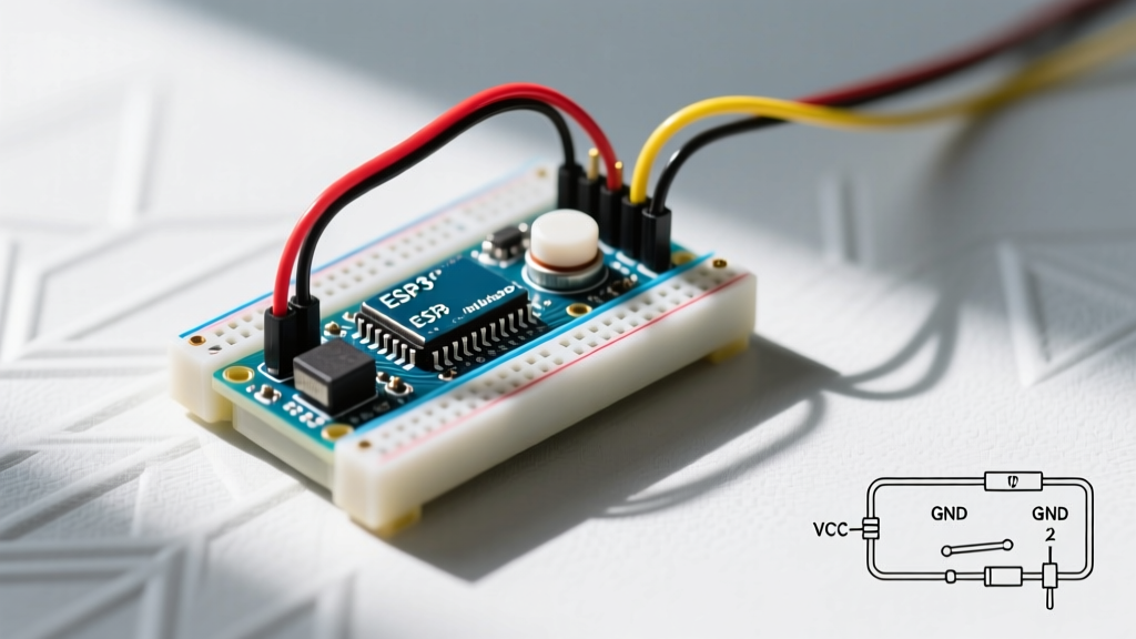
- Insert the Switch: Place your tactile switch across the center trench of your breadboard so that each pair of legs is on a separate side.
- Connect Ground: Run a jumper wire from one leg of the switch to the GND rail on your breadboard. Connect the breadboard GND rail to the Arduino GND pin.
- Connect Signal: Run a jumper wire from the opposite leg of the switch to Digital Pin 2 on your Arduino.
- Verify Connections: Ensure no other components are sharing Digital Pin 2, as stray capacitance can affect debounce timing.
For official documentation on configuring digital pins and utilizing the internal resistors, consult the Arduino Digital Pins Documentation.
The Debounce Dilemma
When you press a mechanical switch, the metal contacts do not meet cleanly. They physically bounce against each other, microscopic welds break and reform, and the electrical signal oscillates between HIGH and LOW for a period of 1 to 50 milliseconds before settling. If your Arduino sketch polls the pin during this window, a single button press will register as a dozen rapid clicks.
While the official Arduino delay() function is often taught as a quick fix for debouncing, it is a terrible practice for any project requiring concurrent operations. Blocking the main loop for 50ms means your microcontroller is blind to sensors, motors, and serial communication during that entire window.
Implementing Non-Blocking Debounce with Bounce2
The professional approach is to use a state-machine-based library like Bounce2. This library tracks the pin state in the background without halting the CPU. Below is the optimal configuration for a single push button for Arduino using this library.
#include <Bounce2.h>

// Instantiate a Bounce object
Bounce debouncer = Bounce();

const int BUTTON_PIN = 2;
const int LED_PIN = 13;

bool ledState = false;

void setup() {
  // Configure the internal pull-up resistor
  pinMode(BUTTON_PIN, INPUT_PULLUP);
  pinMode(LED_PIN, OUTPUT);

  // Attach the pin to the debouncer and set a 10ms debounce interval
  debouncer.attach(BUTTON_PIN);
  debouncer.interval(10);
}

void loop() {
  // Update the debouncer state machine
  debouncer.update();

  // Detect the exact moment the button is pressed (Falling edge due to pull-up)
  if (debouncer.fell()) {
    ledState = !ledState; // Toggle state
    digitalWrite(LED_PIN, ledState);
  }

  // Your main loop can continue running other tasks here without delay
}
By using the fell() method, we specifically target the transition from HIGH to LOW, ignoring all the mechanical noise that occurs during the bounce window. For an in-depth analysis of switch bounce waveforms and hardware vs. software solutions, All About Circuits provides an excellent technical breakdown.
Advanced Troubleshooting & Edge Cases
Even with perfect code, physical environments can sabotage your switch configuration. If your push button for Arduino is still misbehaving, check these specific failure modes:
1. Long Wire Capacitance and Ghosting
If your push button is located more than 2 feet (60 cm) away from the Arduino via unshielded ribbon cable, the wire acts as a capacitor. When the switch closes, the wire must discharge through the microcontroller pin. If the wire is too long, the discharge time can exceed the debounce window, causing missed inputs or ghost triggers. Fix: Add a 1kΩ series resistor between the switch and the Arduino pin, and a 100nF ceramic capacitor in parallel with the switch to create a hardware RC low-pass filter.
2. Contact Oxidation in High-Humidity Environments
Cheap, unbranded tactile switches often use tin-plated brass contacts rather than silver-clad or gold-plated contacts. In humid environments, these oxidize rapidly, increasing contact resistance to over 100Ω. This can cause voltage drops that fail to pull the pin fully to GND. Fix: Specify switches with silver-clad or gold-plated contacts (like the C&K PTS645 series) for outdoor or greenhouse automation projects.
3. Electromagnetic Interference (EMI) from Relays
If your Arduino is switching high-current inductive loads (like motors or solenoids) via relays, the back-EMF spike can couple into the button wiring, tricking the microcontroller into reading a button press. Fix: Route switch wires away from high-current paths, use twisted-pair wiring for the switch signal and ground, and ensure your software debounce interval is set to at least 20ms to filter out transient EMI spikes.
Summary
Mastering the push button for Arduino requires moving past the simplistic view of 'open and closed' circuits. By leveraging internal pull-up resistors to eliminate floating pins and utilizing non-blocking state-machine libraries like Bounce2 to handle mechanical contact resonance, you ensure your input hardware is as robust and reliable as your software logic. Whether you are building a simple macro pad or an industrial control panel, these configuration principles remain the bedrock of reliable digital input design.